
Get in touch with DEMIKS Company

Primary Injection Test Sets & High-Current Systems (1000A, 10000A)
We design and fabricate primary injection and continuous temperature rise test systems for commissioning of utility switchgear, circuit breaker trip tests and utility busbar heat runs.
As a specialized electrical test equipment manufacturer, DEMIKS provides high-current tester units for primary current injection testing, circuit breaker test procedures and protective relay verifications at utility substations.
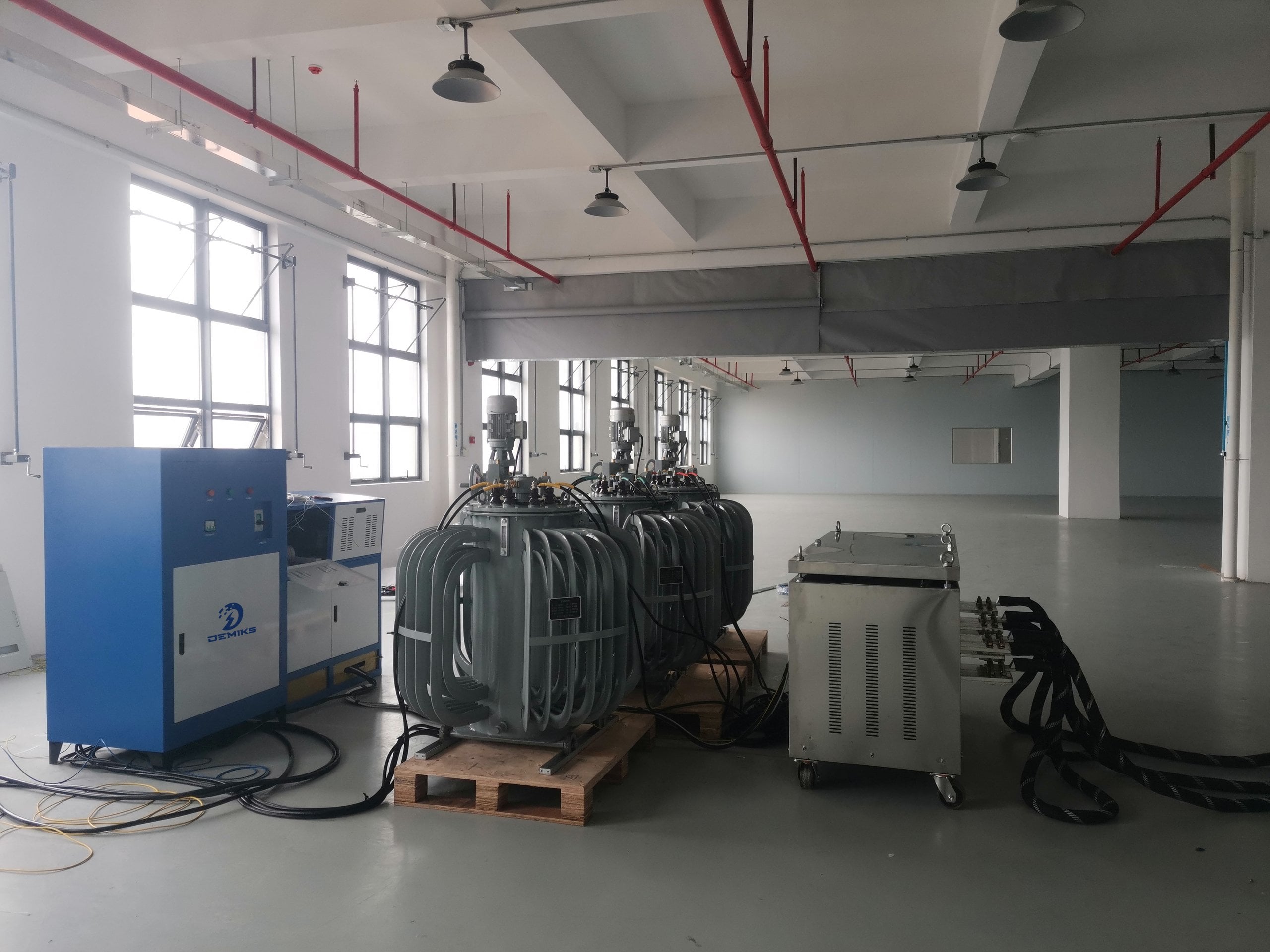
0 to 10,000A True RMS
Smooth motorized induction regulation provides continuous stepless high-current injection for high-voltage testing.
THD ≤ 3% Sinusoid
Pure sine wave output protects sensitive microprocessor-based electronic trip units from nuisance tripping.
Class 0.5 Metrology
High-precision digital shunts and Rogowski sensors ensure ±0.5% full-scale measurement confidence.
8 Export Nations
Field commissioning and on-site operator training by our technical engineers for international Substations.
Primary Injection & Temperature Rise Systems at a Glance
The DDL-WS product family satisfies a wide variety of needs for current injection in compact mobile trolleys and heavy multi-bay testing platforms.
Every high-current product in our portfolio is a precision testing device, and the modular designs allow field engineers to quickly configure single phase or three phase systems without large bulky enclosures.
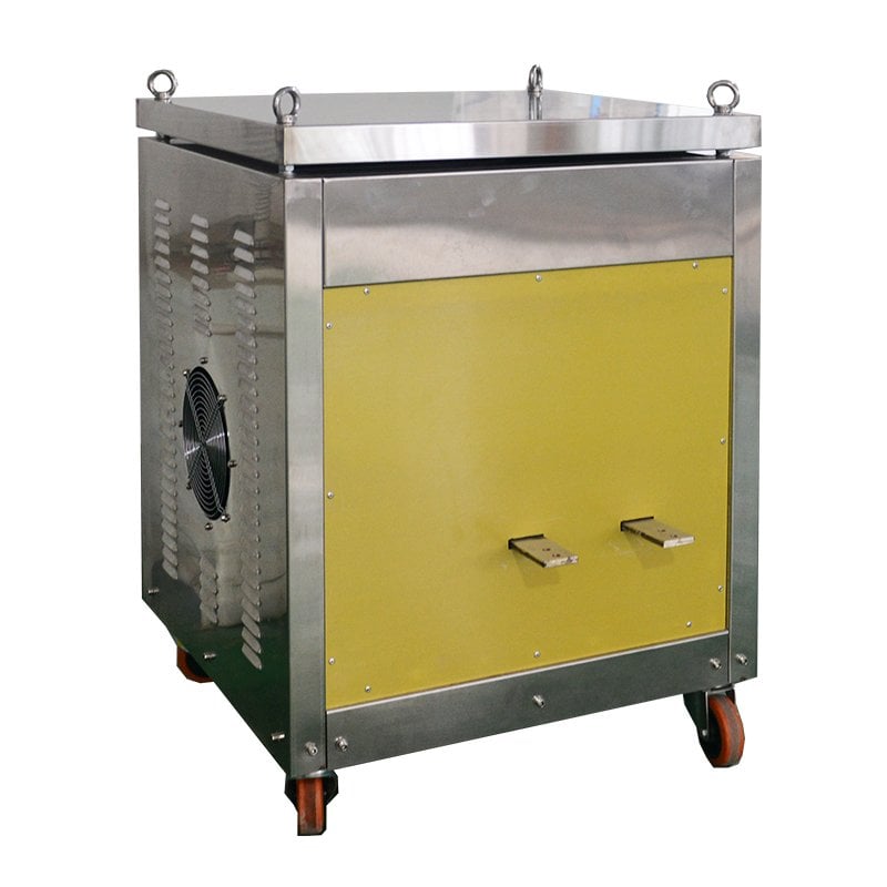
DDL-WS-1000A / 1500A
Our portable single-phase injection systems are designed for field service and testing of low-voltage breakers.
- Current output: 0–1,000A / 1,500A continuous
- Compact trolley chassis for rapid transport
- Integrated digital timing and current display
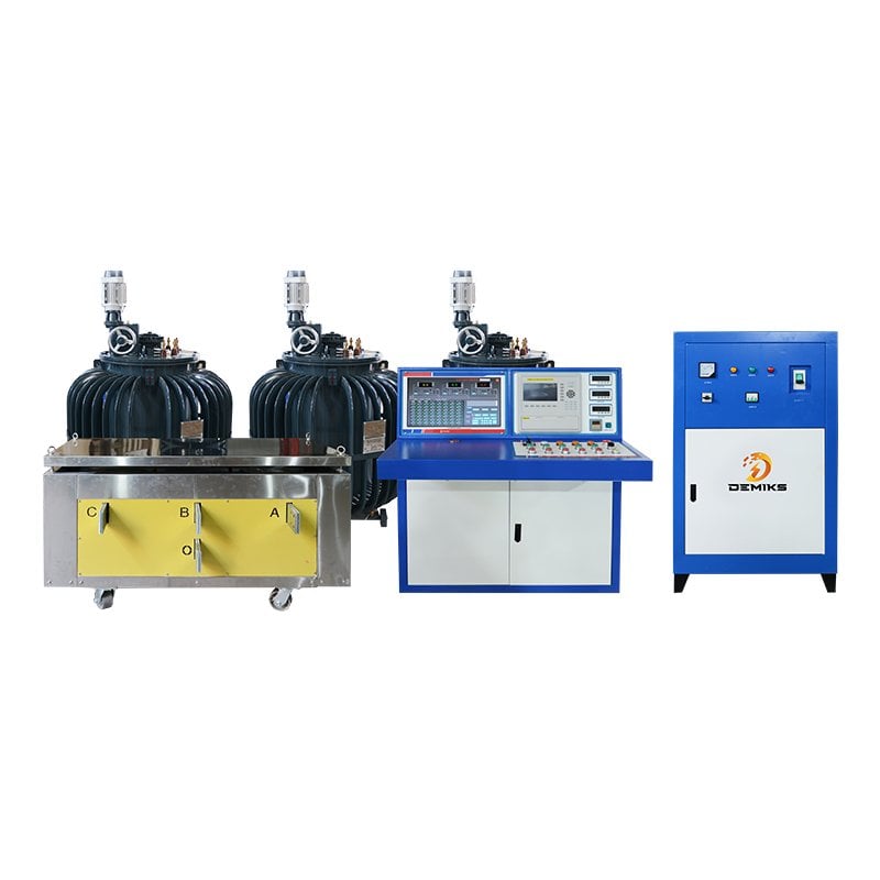
DDL-WS-4000S Three-Phase
Dedicated three-phase current injection sets for medium voltage switchgear and busbar assemblies.
- Current output: 0–4,000A three-phase balanced
- Simultaneous three-phase primary injection
- Motorized voltage regulator with PLC interface
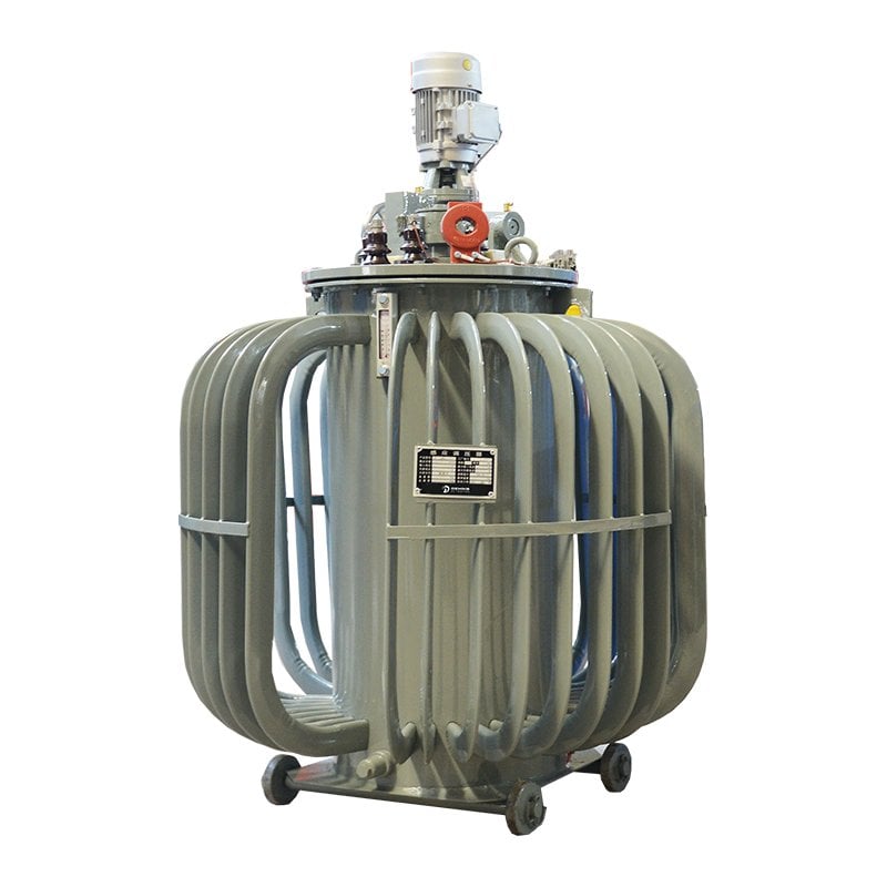
DDL-WS-5000A / 6000A
Heavy-duty high-current generators for testing high-voltage disconnector contacts and thermal cycle verifications.
- Continuous full-capacity thermal endurance
- Inductive transformer core design
- Multi-tap secondary output voltage matching
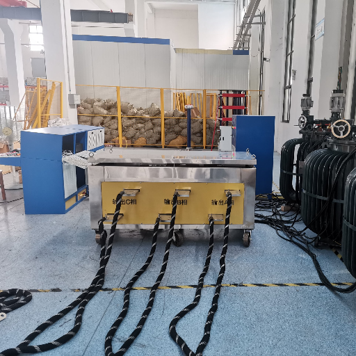
DDL-WS-10000S Utility System
Full-scale engineering primary injection and heat run systems for major utility Substations and Testing Facilities.
- High current output up to 10,000A true RMS
- Complete safety interlocks and remote control
- Customizable busbar clamping fixtures
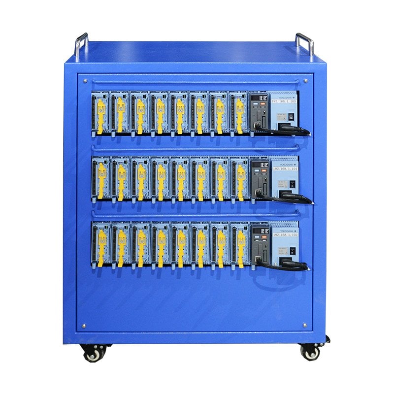
DWS-700 Multi-Channel Logger
Thermocouple temperature rise monitoring system coupled with DDL-WS current generators.
- Measurement range: 0 to 1370℃ with ±1% accuracy
- Automated thermal equilibrium (≤ 1 K/h) logging
- Real-time multi-point heat run curve export
Standards & Testing Duty: Trip Curve Verification vs. Continuous Temperature Rise (Heat Run)
Field commissioning engineers must evaluate the operational difference between momentary protective trip tests and multi-hour thermal endurance heat runs in accordance with EN 62475 and EN 60076-2 standards to avoid equipment overheating.
Why Short-Time Trip Tests Cannot Replace Continuous Heat Runs
A momentary 10-second breaker trip verification cannot replace a 4-hour temperature rise heat run. One of the main reasons for field test failure is a power supply that is not large enough to continuously current, resulting in uncontrolled winding temperatures. It is not appropriate to use short-time injection data to certify continuous busbar ampacity. It creates an undue and unnecessary risk for a sustained terminal thermal runaway condition that could lead to catastrophic contact melting.
Why Pure Sinusoidal Waveforms (≤ 3% THD) Matter in Substation Testing
Modern electronic trip units rely on digital true-RMS sampling algorithms. Waveforms with high harmonic distortion cause false peak-detection tripping. Our motorized induction voltage regulator is specified for ≤ 3% THD to minimize waveform-related measurement error.
| Testing Aspect | Breaker Trip Verification (Short-Time Duty) | Temperature Rise / Heat Run (Continuous Duty) |
|---|---|---|
| Testing Objective | Verify the applicable instantaneous, short-time, and long-time trip curves on circuit breakers. | Measure thermal equilibrium on busbars, contacts, and cables under 100% continuous full-load current. |
| Current Duration | 0.1 second to 60 seconds at elevated multiples of rated current (2x to 10x). | Continuous steady current for 4 to 8 hours until thermal stabilization is achieved. |
| Equilibrium Criterion | Not applicable; thermal memory reset observed between successive trip injections. | Temperature rate of rise ≤ 1 K per hour across all monitored points (DWS-700 automated tracking). |
| Primary Standards | IEC 62475 (high-current measurement systems), IEEE C37.09 (circuit breaker test procedures), and regional field commissioning codes. | IEC 62271-1 (Clause 6.5 switchgear), IEC 60076 (power transformers), and IEEE standards. |
Equipment Cost Drivers & Voltage Regulator Architecture: Motorized Induction vs. Electronic Sources
In order to achieve the required current for testing, there is a balance between the highest allowable compliance voltage and the long-term cost of ownership due to severe environmental conditions of a substation.
When compared to legacy Megger systems, each heavy-duty feature of our motorized regulator delivers reliable performance across diverse substation environments. Understanding the engineering trade-off is essential: an undersized test set with low open-circuit compliance voltage saves upfront weight, but costs you extensive commissioning delays when reactive voltage drop chokes current delivery. To push rated current through 15-meter field cable runs. Heavy motorized induction transformers are not interchangeable with solid-state electronic converters across a dirty substation environment.
Electromagnetic induction regulation is more durable when breaking inductive busbar loads.
- Brushless Electromagnetic Coupling: Zero carbon brush friction and zero commutator carbon dust buildup.
- Inductive Back-EMF Tolerance: Breaker opening can generate a voltage surge in an inductive test loop, requiring adequate output-circuit voltage withstand and transient protection.
- Total Lifecycle Cost: Extremely low maintenance requirements over 15+ years of continuous service.
Electronic variable-frequency sources, while offering flexible programming, are relatively open to failure on high voltage installations.
- Back-EMF Vulnerability: High di/dt voltage transients during circuit clearing risk damaging semiconductor IGBT switches.
- Harmonic Sensitivity: Requires complex output filtering stages which increase system weight and capital cost.
- Replacement Expenses: Repair costs and obsolescence of the components used over the utility deployment cycle increases costs.
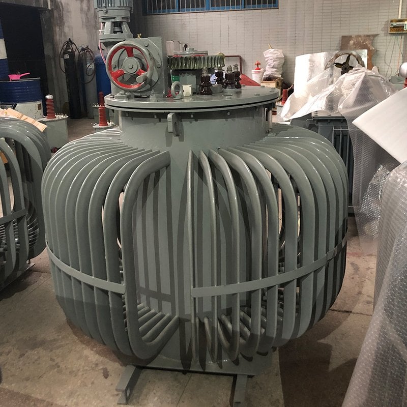
Understanding Open-Circuit Compliance Voltage: Delta V = I * Z_loop
Driving 5,000A through 15 meters of flexible test leads involves cable resistance and inductive loop reactance. Insufficient compliance voltage prevents system from pushing rated current. We pre-engineer compliance voltage taps to account for real test loop impedances.
Technical Specifications & System Comparison Matrix (1000A to 10000A)
Review standard parameters across our primary current injection series configured in compliance with EN 62475 high-current measurement standards. We match secondary voltage windings to your loop impedance.
Incorrect selection of compliance taps is a common cause of field test failure. When test cable runs exceed 10 meters, resistive and inductive voltage drops can limit injection current if the test set lacks sufficient compliance voltage.
| Model Code | Topology | Current Capacity | Compliance Voltage | Measurement Accuracy | Waveform THD | Cooling Method |
|---|---|---|---|---|---|---|
| DDL-WS-1000A | Single-Phase | 0–1,000A RMS | 0–6V (Single Tap) | Class 0.5 (±0.5% F.S.) | ≤ 3% | Forced Air Cooling |
| DDL-WS-1500A | Single-Phase | 0–1,500A RMS | 0–6V / 0–10V | Class 0.5 (±0.5% F.S.) | ≤ 3% | Forced Air Cooling |
| DDL-WS-4000S | Three-Phase | 0–4,000A / Phase | 0–6V / 0–12V | Class 0.5 (±0.5% F.S.) | ≤ 3% | Forced Air Cooling |
| DDL-WS-5000A | Single-Phase | 0–5,000A RMS | 0–8V / 0–15V | Class 0.5 (±0.5% F.S.) | ≤ 3% | Oil/Air Dual Cooling |
| DDL-WS-10000S | Single/Three-Phase | 0–10,000A RMS | 0–10V / 0–18V Custom | Class 0.5 (±0.5% F.S.) | ≤ 3% | Oil-Immersed Forced Air |
| DWS-700 | Multi-Channel | Up to 32 Channels | 0 to 1370℃ Range | ±1% Accuracy | Thermocouple J/K/T | Natural Convection |
Standard power supply input is 380V 50Hz. Customized input voltages (400V, 440V, 480V) and 60Hz grid compatibility are engineered upon project request.
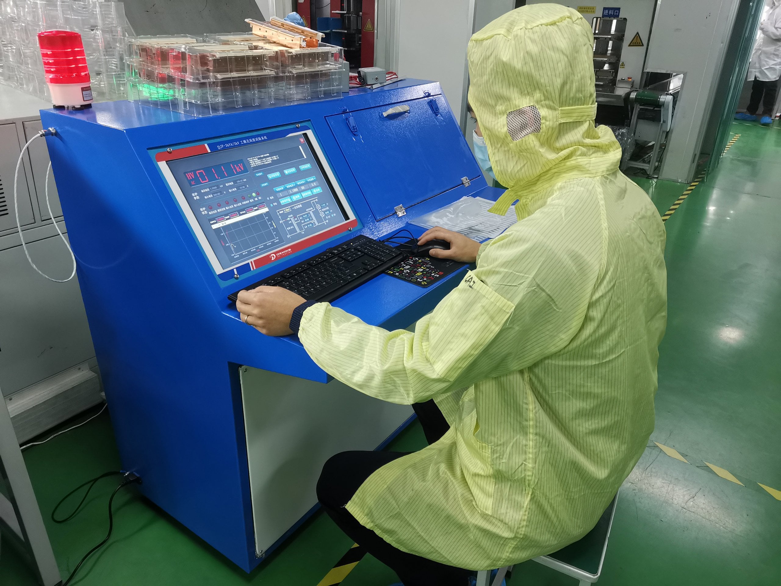
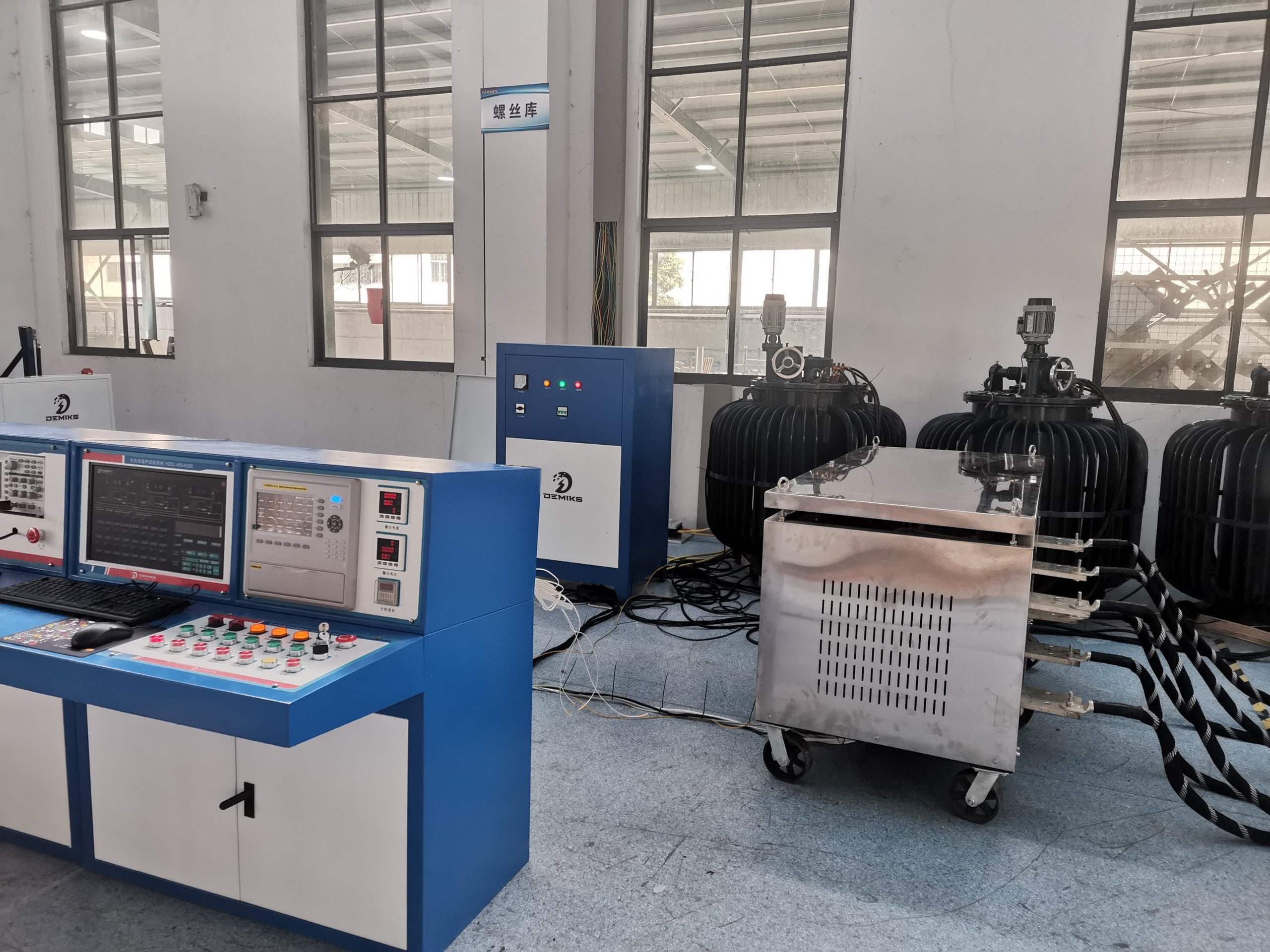
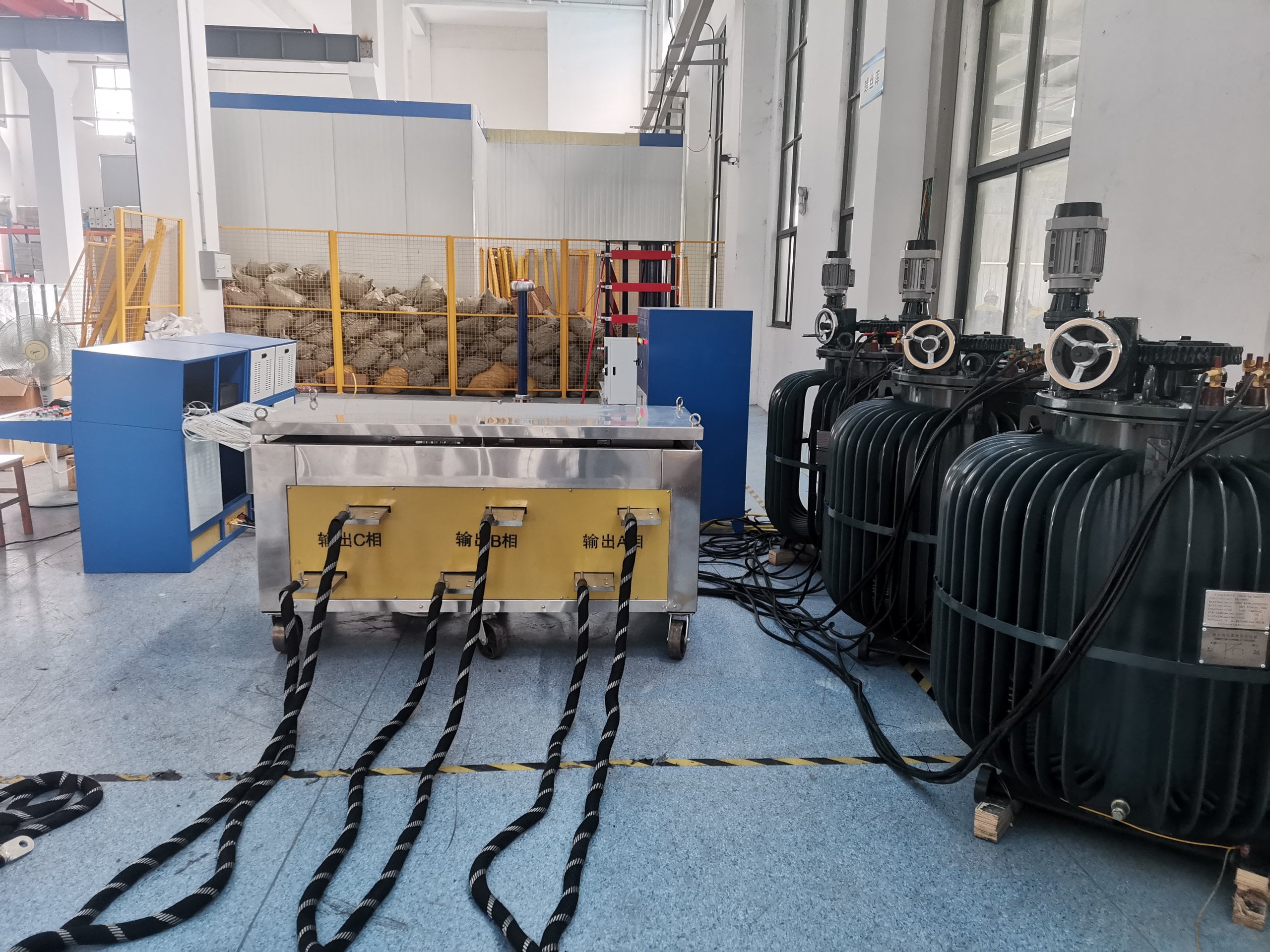
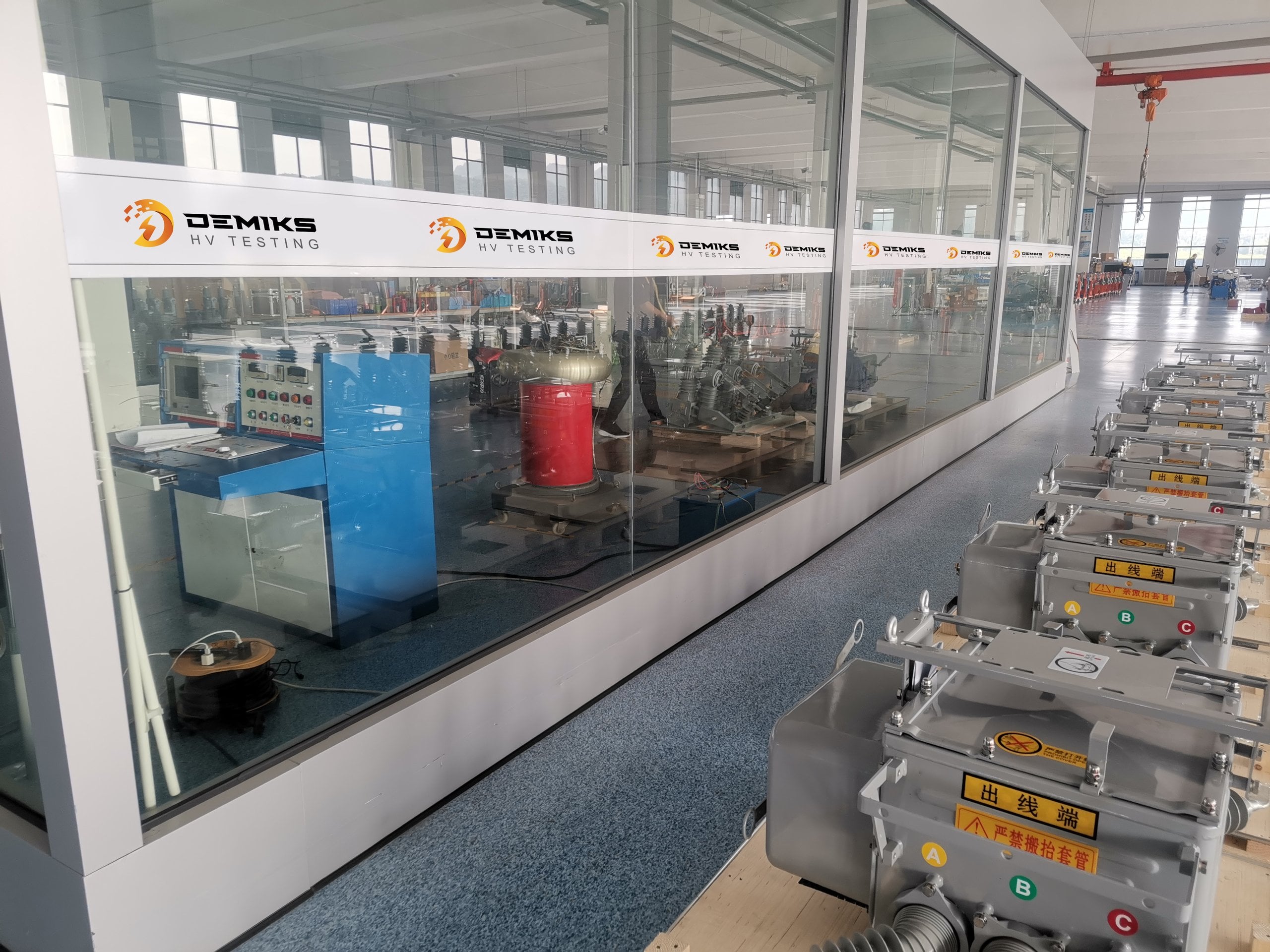
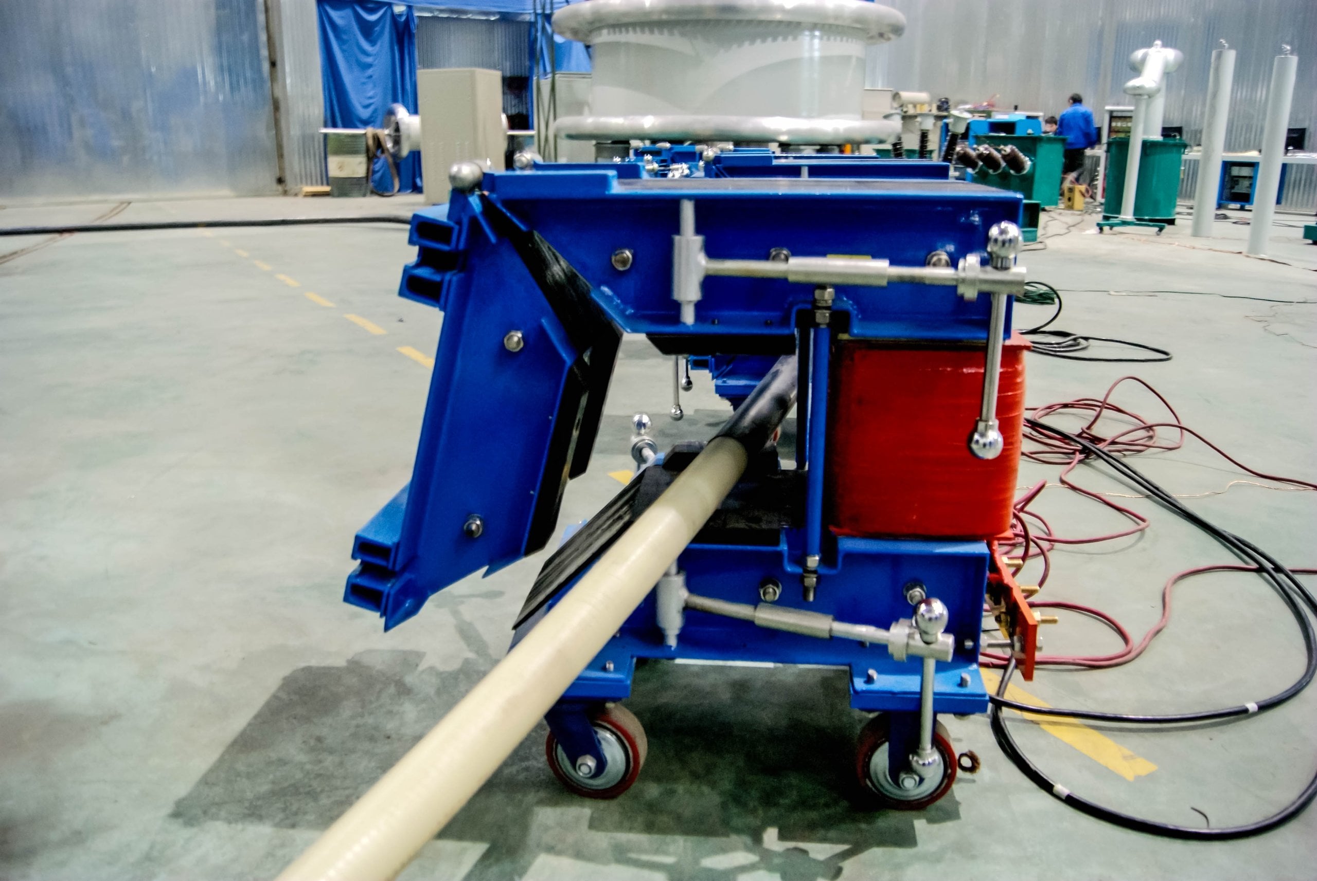
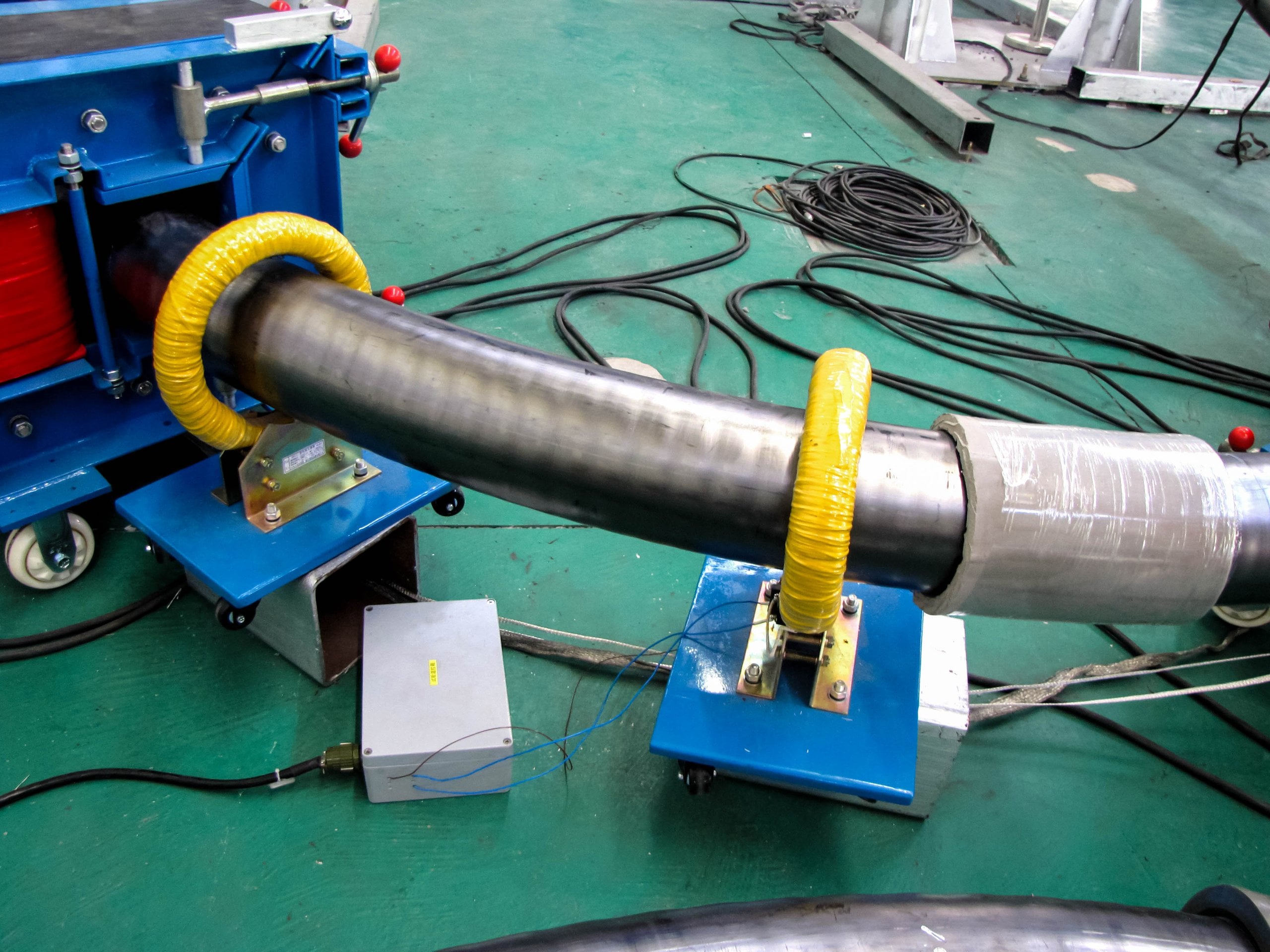
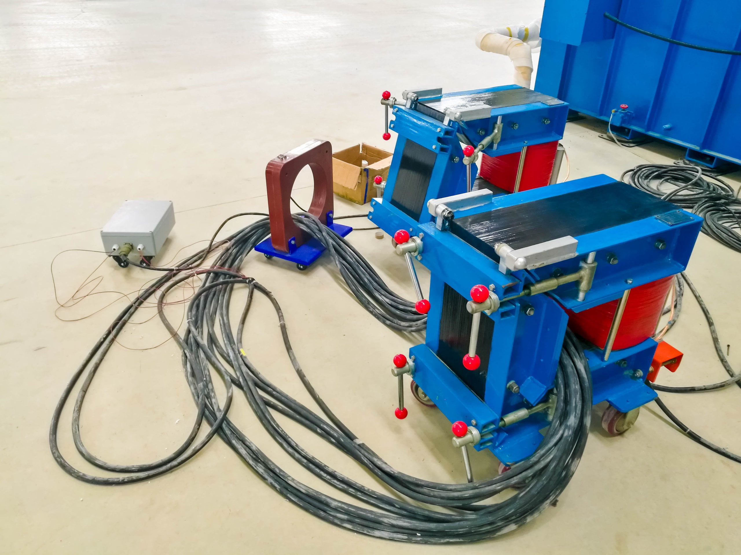
Precision Manufacturing Facilities & High-Current Testing Solutions
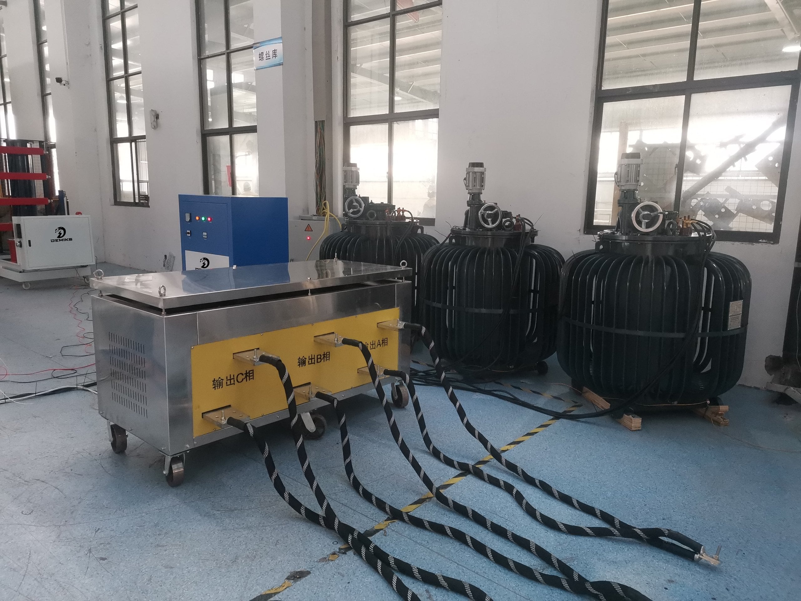
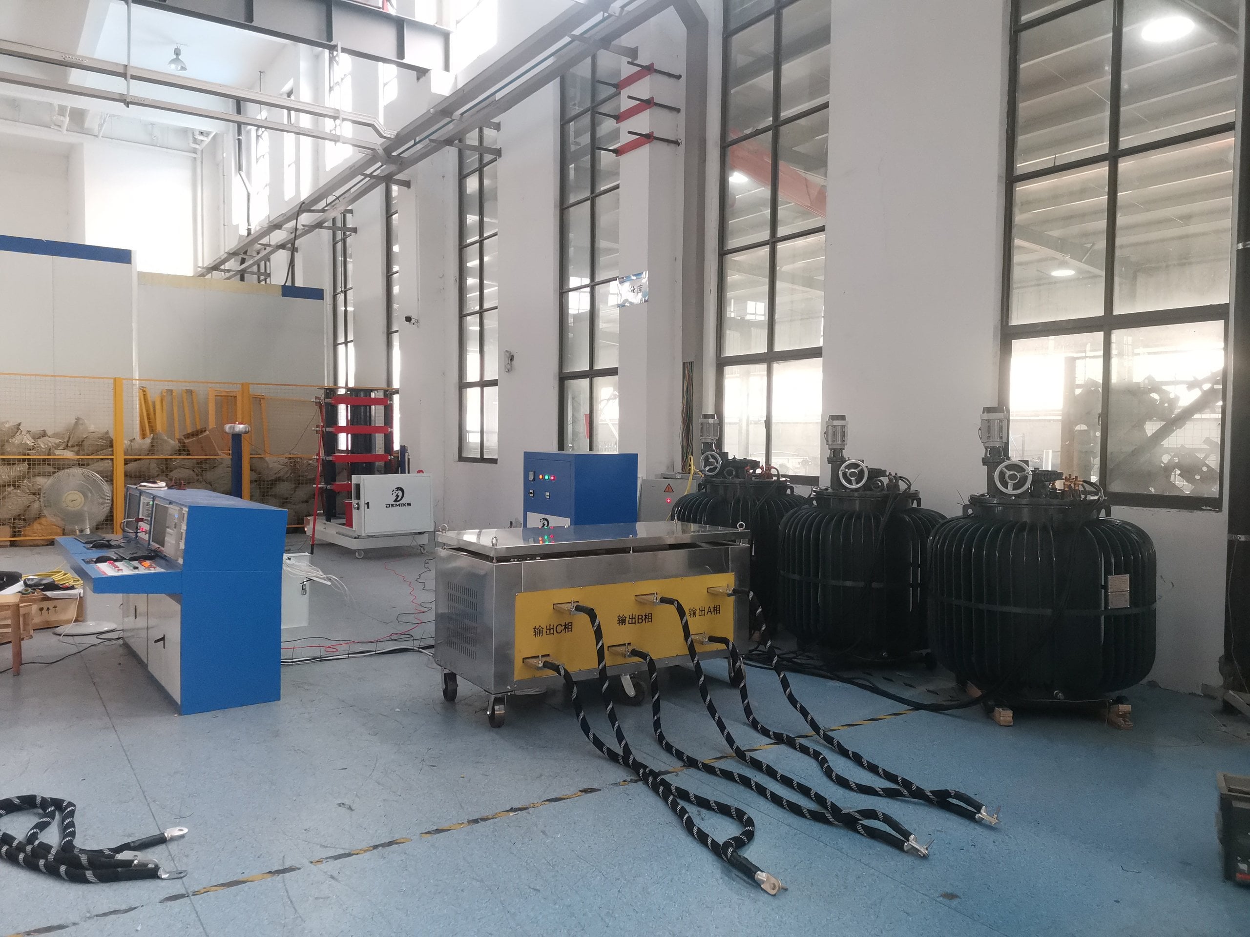
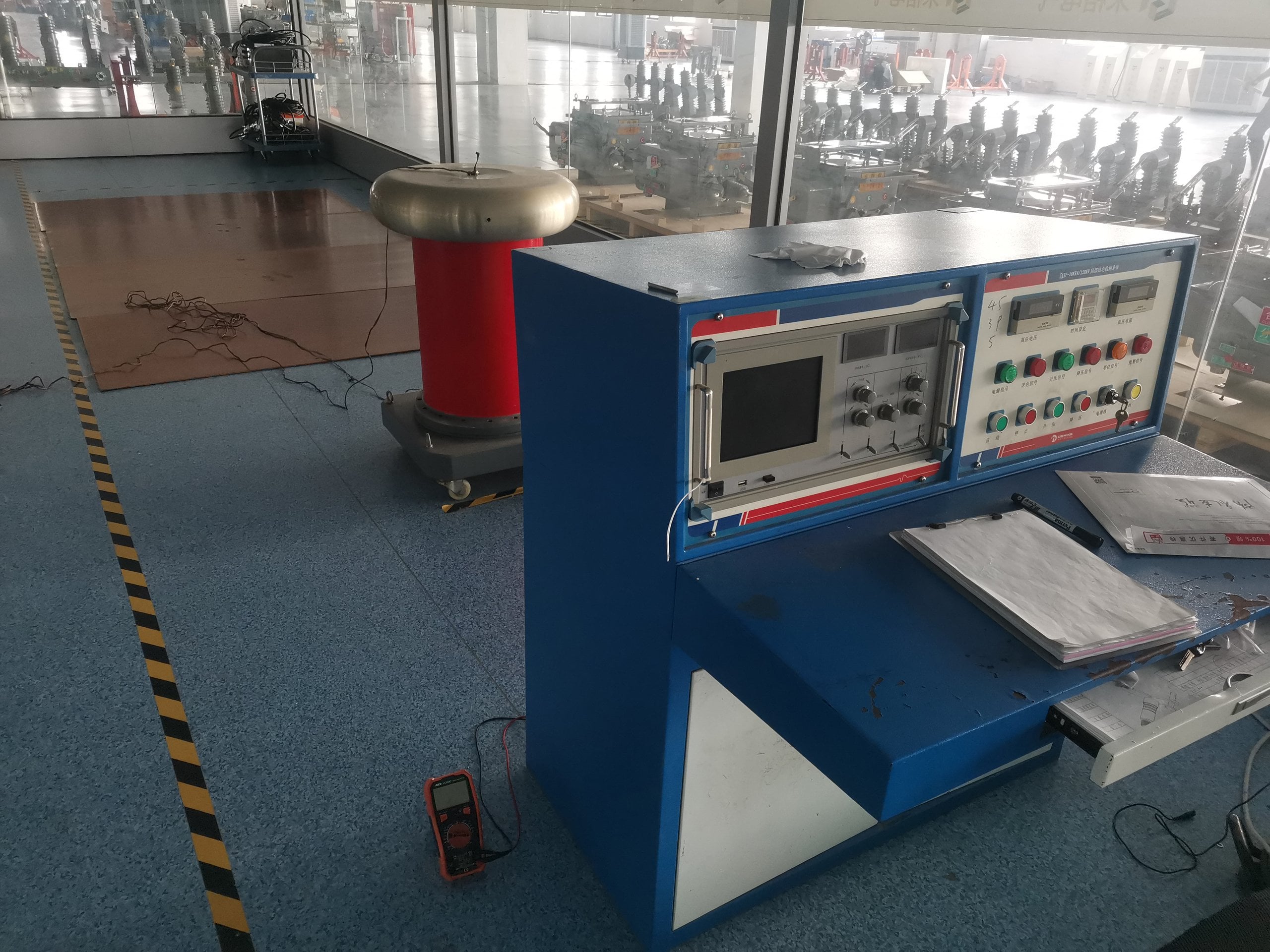
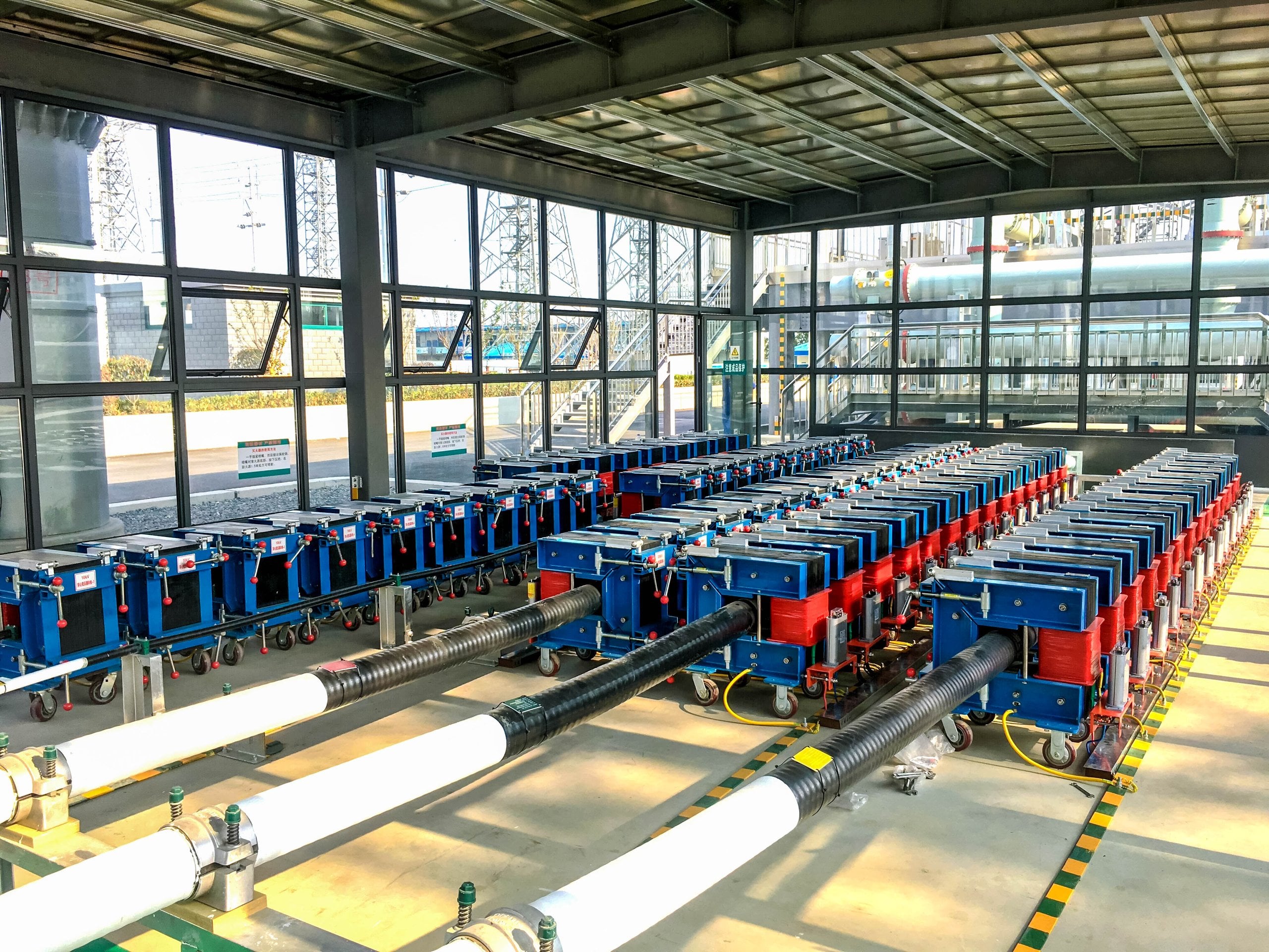
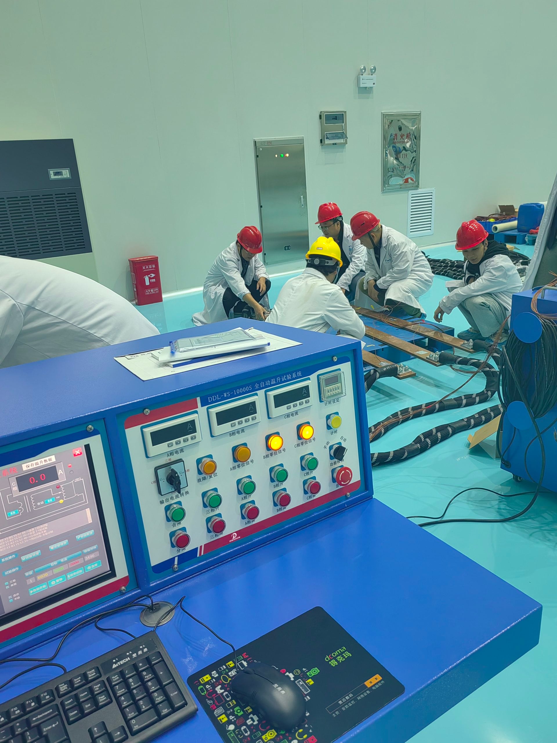
Manufacturing Lead Times & Custom System Engineering (1000A to 10000A)
We perform precision manufacturing and full functional testing of our products at our Shanghai factory. We ensure our products meet the required standards and specifications before exporting them to our customers.
Standard Test Sets
The production timeline is confirmed upon review of detailed technical specifications and equipment capacity agreements.
- Core transformer winding assembly
- Microprocessor controller integration
- Traceable Class 0.5 current calibration verification
Integrated DDL-WS + DWS-700
Production is scheduled based on multi-channel thermocouple configuration and data interface requirements.
- Multi-point thermocouple calibration
- Synchronous PLC data logging validation
- Continuous thermal heat run dry-test
10,000A Custom Installations
Production timeline: established in project contract for high-power utility substation deployments.
- Heavy copper busbar custom fabrication
- Multi-tap secondary compliance design
- High-voltage dielectric isolation testing
Outage Support & Emergency Technical Reviews
Facing tight substation turnaround schedules? Our technical team is available to perform an engineering review of your test cables and breakers upon request.
Factory Acceptance Testing (FAT), Class 0.5 Calibration & Export Shipping Documentation
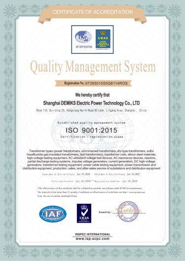
Each system leaves the factory supported by a complete documentation dossier proving measurement and electrical safety under ISO 9001 quality management and ISO 17025 calibration guidelines.
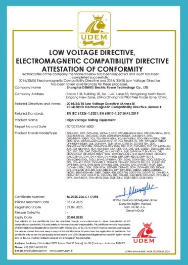
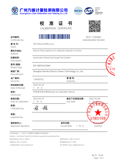
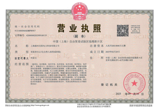
Complete Quality Verification Package
Each test set shipment is complemented by verified documentation for quality assurance purposes.
- Factory Inspection & Test Certificate: Individual equipment test log confirming full-load performance.
- Class 0.5 Calibration Verification Report: Traceable current and voltage metrology across operating ranges.
- Engineering Schematics: Complete electrical wiring diagrams, terminal plans, and layout drawings.
- Operational & Maintenance Manual: Detailed technical operating procedures and safety guidelines.
- Export Packing Dossier: Seaworthy wooden case packing lists and technical inspection sheets.
Remote Video Witness FAT Protocols
International clients can witness live full-capacity Factory Acceptance Tests via secure video links prior to shipment.
- Live primary current injection of up to 10,000 A demonstrated with resistive-inductive load banks.
- Step-by-step verification of waveform distortion and digital Class 0.5 meter readings.
- On-site review of safety interlocks and emergency stop circuits.
Qualifying High-Current Test Set Manufacturers: Direct Factory Engineering & On-Site Global Support
Using uncalibrated and inadequately sized high-current test equipment without ISO 9001 certified manufacturing quality introduces a high-risk situation for the utility commissioning team. This can cause outage penalties and commercial downtime exceeding $15,000 per day.
"In specifying a primary injection test set for long-duration heat runs, compliance voltage needs to be established based on loop impedance. Undersizing compliance voltage is the main reason systems do not reach rated amperage on site." — DEMIKS Chief High-Voltage Test Engineer
Unlike commodity trading intermediaries, Shanghai DEMIKS Electric Power Technology Co., LTD engineers each test system directly at our production base in the Lingang Special Area of the China (Shanghai) Pilot Free Trade Zone. The differentiator of our engineering approach is direct factory accountability: our DDL-WS test sets are engineered to satisfy IEC 62475 high-current measurement standards and IEC 62271-1 heat run protocols, calibrated by an accredited lab. What buyers get wrong when sourcing high-current equipment is assuming all suppliers verify loop impedance compliance. DEMIKS engineers eliminate the disconnect between manufacturers and buyers because we deliver verified Class 0.5 calibration and international field commissioning services.
Established Global Export Record
Our high-voltage and primary current testing systems have been exported and deployed in 8 international countries.
- North America: Utility and industrial testing labs in the United States and Canada.
- Latin America: Proven installations across Brazil, Peru, and Argentina.
- Europe: Active commissioning systems delivered to France, Italy, and Bulgaria.
On-Site Global Engineering Support
For international projects, we send technical engineers to provide complete on-site service.
- On-site system installation and secondary cabling configuration.
- Commissioning and functional load-testing on client switchgear.
- Hands-on operational training for local electrical testing technicians.
- The cost for on-site service depends on the number of engineers and the required duration.
Technical FAQ & Engineering Decision Guide
Compliance voltage must overcome both cable resistive drop and inductive loop reactance (Delta V = I * sqrt(R^2 + (2*pi*f*L)^2)). Driving a 5,000 A load over 15 m of cable makes the reactive drop significant. To lessen the drop, the area of the loop needs to be reduced by bundling the leads tightly. Also, the multi-tap models need to be used to provide compliance voltage. The heavier models provide a compliance voltage of 15V or 18V, and these models are needed to maintain a full test current without transformer saturation.
How do you calculate compliance voltage to push 5,000A through long test cables?
Compliance voltage must overcome both cable resistive drop and inductive loop reactance (Delta V = I * sqrt(R^2 + (2*pi*f*L)^2)). Driving a 5,000 A load over 15 m of cable makes the reactive drop significant. To lessen the drop, the area of the loop needs to be reduced by bundling the leads tightly. Also, the multi-tap models need to be used to provide compliance voltage. The heavier models provide a compliance voltage of 15V or 18V, and these models are needed to maintain a full test current without transformer saturation.
What is the engineering difference between primary and secondary injection?
Secondary injection applies a simulated signal to test protection relay or electronic trip unit logic while bypassing the primary current path and current-transformer primary input. Primary Injection simulates the complete protective system, from primary sensor to mechanical break.
How does the DWS-700 system determine thermal equilibrium during a heat run?
The DWS-700 records multi-point thermocouple readings at programmed intervals according to IEC 60076 and IEC 62271-1 specifications. Thermal equilibrium is confirmed when the temperature rise rate across all critical points is ≤ 1 K per hour.
Can DEMIKS primary injection systems operate on 60 Hz electrical grids?
Our standard manufacturing specification is 380V 50Hz for international utility standards. We readily engineer custom excitation transformers and control circuitry configured for 60Hz power supplies and North American commercial voltages upon project request.
What built-in safety interlocks protect operators during high-current injection?
DEMIKS provides integrated zero-start interlocks, instantaneous over-current trips, thermal cutoff sensors, emergency stops, and/or warning beacons.