
Get in touch with DEMIKS Company

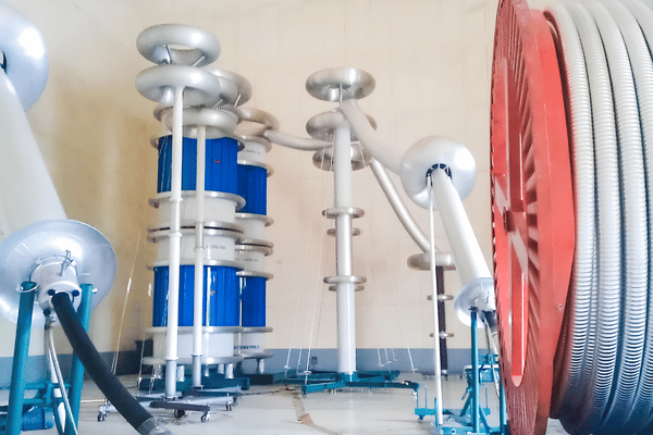
Cable Withstand Voltage Test System
Shanghai DEMIKS Electric Power Technology Co., LTD (DEMIKS) supplies high-voltage electrical equipment for factory, laboratory, and field dielectric verification. Our cable withstand voltage test systems cover extruded XLPE cables rated from 6 kV to 500 kV across 20–300 Hz. We size systems from cable voltage rating (U0/U), conductor cross-section (mm²), capacitance per kilometer (μF/km), and route length (km).
- 6-hour engineering quote turnaround
- 25 to 45 days production lead time
- ±1.5% RMS accuracy and ≤5 pC PD background
- Sized from U0/U, mm², μF/km and route km
Quotes and preliminary resonant sizing calculations are returned within 6 hours on business days. Minimum order quantity is 1 set, configured specifically to your target cable voltage and capacitance.
- Voltage & frequency range
- 6 kV to 500 kV XLPE cables across 20–300 Hz
- Quote turnaround
- Within 6 hours on business days
- Measurement accuracy
- ±1.5% RMS, 0.1 Hz resolution, ≤1% THD
- Reactor Q & PD level
- Q ≥ 30 (10–100 range), PD ≤ 5 pC, 60-min load
- Delivery lead time
- 25 days standard; 25 to 45 days custom bays
- Calibration & warranty
- CMA and CNAS report + 12-month warranty
Variable-Frequency Series Resonant Architecture and Sizing Capabilities
Long extruded power cable feeders present a high capacitive load that can trip 50/60 Hz transformers. A 500 m length of 66 kV cable was tested at 100 kV AC at 50/60 Hz and was found to present a 470 kVA capacitive load requiring over 1 kA from a single-phase 400 V supply. This problem is addressed by our variable frequency series resonant test system because high-Q reactors can reduce input power by 30 to 80 times.

20–300 Hz Automatic Resonance Tracking
The DBP-DL console sweeps 20–300 Hz with 0.1 Hz resolution to lock onto LC resonance (f0 = 1 / [2π√(LC)]). Resonant reactors achieve quality factor Q ≥ 30 (10–100 range) with system partial discharge background controlled to ≤ 5 pC and continuous 60-minute full-load rating.
Modular Series-Parallel Reactor Stacking
DEMIKS reactors can be stacked in series for voltage or in parallel for current. A single ac resonant test system spans from 10 kV distribution to 220 kV transmission circuits.
A 10 km 400 kV XLPE feeder (2.5 μF) at 276 kV demands 260 A (72 MVA) at 60 Hz. A series resonant test system with Q ≥ 50 cuts active input power to 0.7–1.4 MW. Our high voltage cable testing equipment includes an exciter transformer, capacitive divider, and 65 K thermal-limit reactors built around IEC 60840 and IEC 62067 acceptance criteria.
Cable Testing Applications We Configure
- Medium-voltage distribution feeders (6 kV to 35 kV) use portable cable hipot tester bays (75 kVA / 75 kV to 270 kVA / 54 kV) for 2U0 or 2.5U0 cable ac withstand test runs up to 6 km.
- High-voltage sub-transmission lines (66 kV to 150 kV) use multi-reactor bays (540 kVA / 270 kV to 1000 kVA / 250 kV) for their 60-minute IEC 60840 commissioning tests.
- Extra-high-voltage transmission lines (220 kV to 500 kV) use trailer-mounted resonant bays (2000 kVA / 500 kV+) with UHF/HFCT partial discharge monitoring.
- Factory routine and type test laboratories use low-noise bays (≤ 5 pC background) for cable insulation verification, tan delta test diagnostics, and thermal cycling.
Supported Cable Insulation Types and Voltage Classes
Selecting the incorrect waveform for xlpe cable testing can result in space charge damage or joint failure in service. Extruded polyethylene holds trapped DC space charge with a 2035-second relaxation constant for up to 24 hours, making a DC hipot test the wrong call for aged XLPE. DEMIKS configures each hipot cable tester to match the dielectric physics and IEC standards of your respective cable family.
Submarine, Wind Farm Array & Long Export Feeders
Long submarine or collector cables above 15 km require parallel reactor banks to keep resonant frequency inside the 20–300 Hz IEC window. Send your cable datasheet and route length in your RFQ. Our engineering team calculates the exact reactor tap table within 6 hours on business days.
MV Extruded XLPE, TR-XLPE & EPR Cables (6 kV, 35 kV)
| Rated U0/U classes | 3.6/6 kV, 6/10 kV, 8.7/15 kV, 12/20 kV, 18/30 kV, 21/35 kV (Um up to 42 kV) |
| Why engineers pick it | Matches 50/60 Hz operational stress under IEC 60502-2 Clause 20.2 (2U0 or 2.5U0 for 15–60 min) without space-charge polarization. |
| Reactor configuration | 2 to 4 modular epoxy-cast reactors (27 kV / 2.5 A each) in series-parallel combinations |
| Relative system cost | $ – $$ (portable skid or van-mounted package) |
| Standard lead time | 25 days after technical confirmation |
HV Extruded XLPE Power Cables (66 kV, 150 kV)
| Rated U0/U classes | 36/66 kV, 64/110 kV, 76/132 kV, 87/150 kV (Um = 72.5 kV to 170 kV) |
| Why engineers pick it | Complies with IEC 60840 Clause 16.3 (20–300 Hz AC withstand test for 60 min at 1.7U0 or tabulated levels) plus PD monitoring. |
| Reactor configuration | 4 to 8 oil-immersed or dry reactors (67.5 kVA to 250 kVA per stage) with corona spinning rings |
| Relative system cost | $$$ (substation mobile cart or flatbed configuration) |
| Standard lead time | 25 to 45 days depending on voltage rating and reactor count |
EHV Extruded XLPE Transmission Cables (220 kV, 500 kV)
| Rated U0/U classes | 127/220 kV, 160/275 kV, 190/330 kV, 220/400 kV, 290/500 kV (Um up to 550 kV) |
| Why engineers pick it | Applies 20–300 Hz sinusoidal stress per IEC 62067 and CIGRE TB 841 without breaching the 30 kV/mm joint interface ceiling. |
| Reactor configuration | High-Q modular reactor towers on insulating frames with ≤ 5 pC background noise |
| Relative system cost | $$$$ – $$$$$ (engineered multi-reactor bay or trailer system) |
| Standard lead time | 45 days for custom extra-high-voltage systems |
PILC Laminated Cables & Extruded Cable Oversheaths
| Rated classes | Paper-insulated lead-covered (PILC) feeders and PE/PVC outer jackets on HV/EHV XLPE cables |
| Why engineers pick it | Executes IEC 60229 Clause 5 DC oversheath voltage testing (4 kV/mm up to 10 kV DC for 1 min) and insulation resistance checks before AC resonance. |
| Equipment pairing | Companion DC voltage sheath fault locator and megohmmeter bundled into the commissioning package |
| Relative system cost | $ (auxiliary module or standalone sheath tester) |
| Standard lead time | 25 days after technical confirmation |
STANDARDS & PROTOCOLS
Test Methods, International Standards, and Diagnostic Protocols
Approximately 68-75% of HV extruded cable failures occur in field joints and terminations during the first 3 years of service. A simple go/no-go voltage test, however, does not detect partial discharge defects that occur between the voltage levels of 1.0 U0 to 1.7 U0. Combining 20-300 Hz AC resonance with PD and tan delta diagnostics prevents outages that occur after commissioning.
| Test method / protocol | Governing standard | Target parameter & waveform | In-house or partner |
|---|---|---|---|
| Variable-Frequency AC Series Resonance (MV) | IEC 60502-2 Clause 20.2 / ANSI/NETA ATS-2025 | 20–300 Hz sinusoidal AC at 2U0 (or 2.5U0) for 15–60 min; THD ≤ 1% | In-house DEMIKS DBP-DL system + CMA/CNAS calibration |
| HV Extruded Cable AC Withstand Test | IEC 60840:2020+AMD1:2023 Clause 16.3 Table 12 | 20–300 Hz sinusoidal AC at 1.7U0 (or tabulated kV) for 60 min continuous load | In-house DEMIKS DBP-DL system + CMA/CNAS calibration |
| EHV Extruded Cable AC Withstand Test | IEC 62067:2022 Clause 16.3 / CIGRE TB 841 | 20–300 Hz sinusoidal AC at 1.1–1.7U0 for 60 min; interface stress < 30 kV/mm | In-house DEMIKS EHV resonant bay + CMA/CNAS calibration |
| Synchronized Partial Discharge (PD) Diagnosis | IEC 60270 / IEC 60885-3 / CIGRE TB 841 | System background ≤ 5 pC; HFCT/UHF joint-hopping detection down to 5–10 pC | In-house DEMIKS low-PD divider & offline PD detector |
| 0.1 Hz VLF Withstand & Tan Delta Diagnostics | IEEE Std 400.2-2024 / IEC 60502-2 | 0.1 Hz sinusoidal or cosine-rectangular up to 3U0 (MV distribution cables ≤ 35 kV) | In-house DEMIKS VLF hipot & tan delta test unit |
| Extruded Cable Oversheath DC Withstand | IEC 60229:2007 Clause 5 | 4 kV DC per mm of jacket thickness (10 kV DC max) held for 1 min before & after AC test | In-house DEMIKS DC sheath tester + CMA/CNAS calibration |
Every system is delivered with an accredited CMA and CNAS third-party inspection report, factory acceptance protocol, and English operating manual. No uncalibrated reactor or divider leaves our facility prior to written acceptance verification.
SPECIFICATIONS
Request a System Sizing Quote
System Specifications, Accuracy Tolerances, and Sizing Envelope
Exceeding 260 kV test voltage on high-voltage circuits or feeding 5000 nF capacitance on 22 km cables causes single-unit testers to hit voltage ceilings. Stacking modular reactors in series and parallel solves both limits. System voltage measurement accuracy is held to ±1.5% RMS with 0.1 Hz frequency resolution and ≤1% total harmonic distortion (THD).
| Specification parameter | What we hold (DEMIKS DBP-DL Series) |
|---|---|
| Supported cable voltage rating | 6 kV to 500 kV extruded XLPE, TR-XLPE, and EPR power cables (U0 from 3.6 kV to 290 kV) |
| Output voltage & capacity envelope | Up to 500 kV AC RMS and 75 kVA to 4000 kVA via modular series-parallel reactor banks |
| Output frequency sweep range | 20–300 Hz continuous automatic/manual tuning (compliant with IEC 60502-2, IEC 60840, IEC 62067) |
| Voltage measurement accuracy | ±1.5% RMS across full scale against accredited reference capacitive divider |
| Frequency resolution & stability | 0.1 Hz tuning step resolution with automatic phase-locked frequency stability at full load |
| Output waveform distortion (THD) | Total harmonic distortion ≤1% pure sinusoidal output waveform across rated load |
| Reactor quality factor (Q) | Q ≥ 30 across 20–300 Hz (30 to 80 on dry/oil reactors; 10–100 system design range) |
| System partial discharge background | ≤ 5 pC at rated test voltage for PD-monitored HV/EHV commissioning configurations |
| Continuous full-load duty & thermal limit | 60-minute continuous full-load rating; reactor winding rise ≤ 65 K, oil rise ≤ 55 K |
| Single-module reactor envelope & protection | 35–65 kg (77–143 lb), Ø320–550 mm × 450–900 mm (12.6–21.7 in × 17.7–35.4 in); flashover trip < 10 ms |
QUOTATION & LEAD TIME
Pricing Drivers, Quotation Turnaround, and Production Lead Times
System price follows target test voltage (Utest), total cable capacitance (Ctotal), charging current (IC), partial discharge noise floor (≤ 5 pC), and trailer mounting. Buying a fixed-frequency transformer for long HV feeders costs you 30 to 80 times more generator capacity. A modular resonant bay buys you multi-voltage versatility across projects.
What Moves Your System Cost
| Cost driver | Effect on system engineering | How to lower your system cost |
|---|---|---|
| Maximum test voltage (Utest) | Determines insulation clearance, divider voltage ratio, and series reactor stage count | Size for your highest confirmed voltage class (e.g., 132 kV at 1.7U0) and use parallel tapping for 11–35 kV feeders |
| Total cable capacitance (C = c × L) | Sets charging current IC = 2πfCU and total kVA capacity of the reactor bank | Use the lower end of the 20–300 Hz IEC frequency window (e.g., 25–35 Hz) on long cables to reduce charging current and required kVA capacity |
| Partial discharge background (≤ 5 pC) | Requires corona-shielded reactors, non-PD capacitive divider, and filtered variable-frequency drive | Specify ≤ 5 pC shielding when testing 66–500 kV transmission joints; use standard shielding for MV go/no-go hipot runs |
| GIS termination frequency window | Restricts test frequency to 50–80 Hz when inductive VT/CT units remain connected | Disconnect electromagnetic voltage transformers during cable testing so the resonant set tunes freely down to 20–30 Hz |
How Your Engineering Quote Is Produced
Quotes and preliminary resonant sizing calculations are returned within 6 hours on business days. Send your cable voltage rating, cross-section, and route length, and a DEMIKS high-voltage engineer returns a formal quotation with a series-parallel reactor tap table at no charge.
Production Lead Times by System Class
| System configuration stage | Confirmed lead time | What it covers |
|---|---|---|
| Standard MV/HV resonant test sets | 25 days | Standard cable withstand voltage test system configurations ship in 25 days after technical confirmation. |
| Multi-reactor series-parallel test bays | 25 to 45 days | Multi-reactor series-parallel test bays ship in 25 to 45 days depending on voltage rating and reactor count. |
| Custom EHV & trailer-mounted bays | 45 days | Custom extra-high-voltage and trailer-mounted cable test systems are delivered in 45 days. |
QUALITY & CALIBRATION
Quality Assurance, Factory Testing, and CMA/CNAS Calibration
International utility buyers and EPC contractors cannot take the risk of voltage drift or thermal detuning during the 60-minute HV cable soak test. Every DBP-DL system is run at full-load and fully tested by an independent third-party metrology before being shipped. Your field crew receives a high voltage cable hipot tester, with verified accuracy and protection interlocks.
How Every System Is Verified Before Shipment
- Each reactor winding and epoxy cylinder is tested for inductance linearity, inter-turn insulation resistance, and a quality factor of Q ≥ 30 across 20 to 300 Hz.
- The assembled variable-frequency console, exciter transformer, and reactor stack run at rated current for 60 minutes during FAT to verify winding rise ≤ 65 K and oil rise ≤ 55 K.
- Background noise is verified to ≤ 5 pC under IEC 60270, while over-voltage, over-current, detuning, and flashover protection trips are timed at < 10 ms.
- Before packing, the complete system is calibrated by an accredited third-party metrology institute to verify ±1.5% RMS voltage accuracy, 0.1 Hz resolution, and ≤1% THD.
Every system ships with a third-party inspection report accredited by CMA and CNAS, factory test protocol, and English operation manual. All DEMIKS cable withstand voltage test systems include a 12-month warranty covering the variable-frequency console, exciter, reactors, and divider.
Nonconformance and Warranty Resolution
If any module fails to meet the written accuracy, Q-factor, or ≤ 5 pC background threshold during factory witness testing, we rework or replace it before dispatch. During the 12-month warranty period, DEMIKS repairs or replaces any nonconforming component against the signed acceptance protocol.
PROCESS
How We Work: Sizing, Factory Verification, and Overseas Commissioning
Overseas EPC contractors experience commissioning delays when high-voltage test sets arrive without phase-matched reactor tap tables or on-site engineer support. As DEMIKS maps every reactor combination to your exact cable schedule prior to production, your field crew avoids job site detuning and generator overload.
- We size systems from cable voltage rating (U0/U), conductor cross-section (mm²), capacitance per kilometer (μF/km), and route length (km).
- Quotes and preliminary resonant sizing calculations are returned within 6 hours on business days, detailing series-parallel reactor connections for every feeder on your schedule.
- Once the technical configuration is confirmed, we build your bay within 25 days for standard sets or 25 to 45 days for multi-reactor and custom EHV systems.
- We execute the 60-minute full-load heat-run, ≤ 5 pC partial discharge check, and independent CMA and CNAS calibration, sharing video and test data for your sign-off.
- Systems are packed in shock-monitored export crates and shipped under EXW, FOB, CIF, or DDP trade terms with full customs and test protocols.
- DEMIKS dispatches engineers for overseas on-site installation, commissioning, and operator training, with independent CMA/CNAS calibration before dispatch.
Field Engineering Rules That Lower Commissioning Cost
| Field test scenario | What to specify in your RFQ | Why it saves time and budget |
|---|---|---|
| Mixed 11 kV, 33 kV, and 132 kV cable schedules | Specify 4 identical modular reactors (e.g., 67.5 kV / 2.5 A per unit) instead of a single 270 kV tank | Allows 4-series connection for 132 kV (270 kV max) and 2-series-2-parallel or 4-parallel connection for long 11–33 kV feeders |
| Testing through GIS terminations with installed VTs | Flag connected inductive instrument transformers so our engineers size for the restricted 50–80 Hz window | Testing through GIS terminations energizes installed instrument transformers whose frequency limits are restricted to 50–80 Hz rather than 20–300 Hz |
| Remote wind farm or desert substation sites | Request Q ≥ 40 reactor design and 380–415 V 3-phase variable-frequency input console | Cuts portable diesel generator requirement from >500 kVA down to a standard 30–75 kVA jobsite generator |
| High-altitude or high-humidity jobsite (>1000 m) | Specify site elevation and ambient temperature (-20°C to +50°C) at quotation stage | Applies high-altitude external air-clearance correction to reactor grading rings and divider flashover distance |
FIELD EVIDENCE
Field Commissioning Evidence and Global Export Footprint
Empirical commissioning data proves why utilities mandate 20–300 Hz series resonant testing before energizing new HV/EHV feeders. Across more than 800 three-phase HV XLPE circuits (36/66 kV to 220/400 kV) tested at 20–300 Hz, 4.5% failed initial commissioning. Main-insulation breakdown or partial discharge in accessories affected 3.1% of all tested circuits.
"A rate of 4.5% of all circuits tested failed in some way during initial commissioning testing, with main insulation failures affecting 3.1% of circuits tested." Aitor Kortajarena & Imanol Loureiro, Tecnalia Electrical Laboratories (INMR Commissioning Study of >800 HV XLPE Cable Circuits)
Industries and Testing Environments We Supply
01 // GRID & SUBSTATION
Utility Substation & Grid Commissioning
On-site 60-minute 20 to 300 Hz AC withstand and synchronized partial discharge testing of 35, 110, 132, 220 and 400 kV underground XLPE feeders.
02 // RENEWABLE COLLECTOR
Renewable Energy & Wind/Solar Collector Lines
High-capacitance series-parallel reactor bays for 33 and 66 kV wind farm collector networks and export cables where long route lengths (5 to 22 km) exceed portable VLF capacity.
03 // FACTORY & LAB
Cable Factory & High-Voltage Test Laboratories
Low-noise (≤ 5 pC) resonant test systems, thermal cycling test benches, and impulse/withstand bays for cable routine testing, sample type testing, and pre-qualification protocols.
Verified Global Export Footprint & Engineering Support
Established in 2025 in the Lingang Special Area of the China (Shanghai) Pilot Free Trade Zone, Shanghai DEMIKS Electric Power Technology Co., LTD supplies high-voltage test equipment worldwide. We have exported systems to Brazil, Peru, Argentina, the United States, Canada, Bulgaria, France, and Italy. For overseas projects, DEMIKS dispatches engineers for on-site installation, commissioning, and operator training, with service fees structured by engineer count and site duration.
BOUNDARIES & SELECTION
When 20–300 Hz AC Series Resonance Is Not the Right Call
A 20–300 Hz variable-frequency series resonant system is not interchangeable with every cable test instrument, and using the wrong method costs you time or damages insulation. Applying 0.1 Hz vlf cable testing or DAC to EHV cables above 150 kV with a 1.5x scale factor breaches the 30 kV/mm maximum interface electrical stress limit. On short MV spurs or outer cable jackets, a simpler tester is not a substitute for engineering judgment and belongs there instead.
| Testing situation | Why 20–300 Hz AC resonance works against you | What to do instead (the right call) |
|---|---|---|
| Short MV distribution spurs (≤ 35 kV, < 1 km) with tight van access | Setting up multi-stage resonant reactors and an exciter transformer takes more rigging time than a single-box VLF set | Use a 0.1 Hz sinusoidal VLF cable hipot tester per IEEE Std 400.2-2024 and IEC 60502-2 Clause 20.2 (3U0 for 15–60 min) |
| Outer PE/PVC cable jacket integrity check after trench pulling | High-voltage AC resonance tests the main XLPE insulation between conductor and screen, not the outer non-metallic oversheath | Run an IEC 60229 Clause 5 DC voltage oversheath test at 4 kV DC per mm of jacket thickness (capped at 10 kV DC for 1 min) |
| Legacy paper-insulated lead-covered (PILC) maintenance feeder | Laminated oil-paper dielectric has high dielectric loss factor and does not suffer from XLPE space-charge trapping | Apply a controlled DC withstand test per IEEE Std 400.1 or a 0.1 Hz VLF test sized for high-loss laminated insulation |
| Aged MV XLPE cable where water-tree grading is required without breakdown | A 60-minute full-voltage withstand test can trigger breakdown in severely water-treed distribution cables during maintenance | Perform a monitored 0.1 Hz VLF tan delta test (tip-up / stability check) coupled with partial discharge mapping first |
TECHNICAL FAQ
Cable Withstand Voltage Test System FAQs
Why do IEC 60840 and IEC 62067 specify 20–300 Hz AC resonant testing instead of DC hipot for XLPE cables?
DC voltage injects trapped hetero space charge into extruded XLPE insulation with a relaxation time constant of 2035 seconds. That trapped charge takes up to 24 hours to dissipate and triggers premature breakdown when AC voltage returns. IEC 60840 (66–150 kV) and IEC 62067 (220–500 kV) therefore require 20–300 Hz sinusoidal AC withstand testing for 60 minutes.
How do I calculate the required kVA capacity and current for a cable ac withstand test?
Charging current equals IC = 2πfCUtest and reactive test capacity equals Q = 2πfCUtest², where C is total cable capacitance (c × L). Because DEMIKS resonant reactors achieve quality factor Q ≥ 30 (10–100 range), the variable-frequency supply only feeds active losses (Pin = QkVA / Q). Send your cable schedule to DEMIKS and our engineers return the complete kVA and reactor tap sheet within 6 hours.
When should we choose 20–300 Hz series resonance over a 0.1 Hz VLF hipot cable tester?
Use a 0.1 Hz VLF tester for short 6–35 kV distribution cables under IEEE Std 400.2-2024. Choose a 20–300 Hz variable frequency series resonant test system for long MV feeders (> 3–5 km) and all HV/EHV XLPE cables from 66 kV to 500 kV. Applying 0.1 Hz VLF scale factors (1.5x) to EHV cables above 150 kV breaches the 30 kV/mm interface stress limit in cable joints.
How do modular reactors adapt to both high-voltage short cables and lower-voltage long cables?
Each DEMIKS DBP-DL system divided total inductance into 2 to 8 identical reactor modules. For series connection, crews increased total module count to multiply voltage (Utotal = n × Umodule) or reduced total module count to multiply current (Itotal = n × Imodule). This maintained the resonant frequency f0 = 1 / (2π√(LC)) within the 20 to 300 Hz IEC window from 100 m to over 20 km.
What happens if GIS voltage transformers remain connected during an AC cable withstand test?
GIS termination tests, as done by us, energize inductive instrument transformers, which have frequency limits of 50-80 Hz, instead of the required 20-300 Hz. When VTs cannot be isolated, our engineers size additional parallel reactor capacity to take care of resonance locks above 50 Hz, without saturating substation cores.
How fast can DEMIKS provide a sizing proposal and deliver the equipment?
Our engineering desk returns formal quotations and preliminary resonant sizing sheets within 6 hours on business days. Standard cable withstand voltage test system configurations ship in 25 days after technical confirmation. Multi-reactor series-parallel test bays ship in 25 to 45 days, and custom extra-high-voltage systems are delivered in 45 days.
What calibration certificates and documents ship with every order?
Every system ships with a third-party inspection report accredited by CMA and CNAS, factory test protocol, and English operation manual. The calibration report verifies ±1.5% RMS voltage accuracy, 0.1 Hz frequency resolution, ≤1% total harmonic distortion (THD), Q ≥ 30, and ≤ 5 pC partial discharge background.
Can DEMIKS dispatch engineers to our overseas jobsite for installation and commissioning?
Yes, DEMIKS dispatches engineers for overseas on-site installation, commissioning, and operator training, with independent CMA/CNAS calibration before dispatch. We have exported high-voltage test equipment to Brazil, Peru, Argentina, the United States, Canada, Bulgaria, France, and Italy. On-site service fees depend on the number of engineers and the time required.
What warranty and trade terms apply to international orders?
All DEMIKS cable withstand voltage test systems include a 12-month warranty covering the variable-frequency console, exciter, reactors, and divider. Orders start at a minimum order quantity of 1 set, engineered around your rated voltage class and feeder capacitance. We ship under EXW, FOB, CIF, or DDP trade terms depending on destination port and project logistics.
RFQ & SIZING
Send Your Cable Parameters for a 6-Hour Engineering Quote
Our engineers calculate reactor and exciter sizing from your cable voltage rating (U0/U), conductor cross-section (mm²), capacitance per kilometer (μF/km), and route length (km). Submit your feeder schedule below and a DEMIKS high-voltage engineer will return a formal quotation and series-parallel reactor tap table within 6 hours on business days.
Engineering quotations and reactor tap sizing sheets are returned within 6 hours on business days. Every system includes a 12-month warranty and a third-party inspection report accredited by CMA and CNAS.
Request a System Sizing Quote