Get in touch with DEMIKS Company

AC Resonant Test Systems: Variable Frequency & Variable Inductance Sets (44 kVA to 540 kVA)
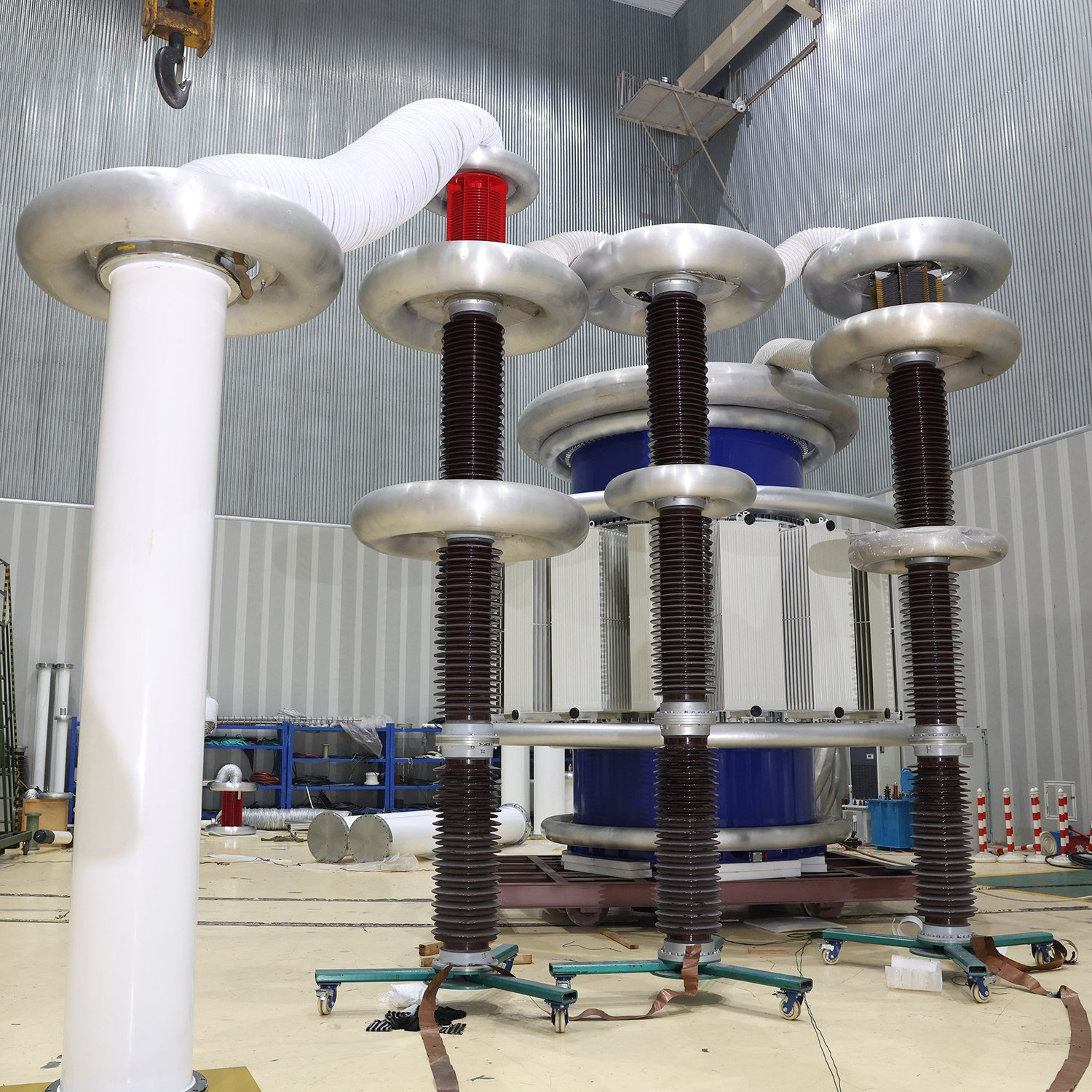
Shanghai DEMIKS Electric Power Technology Co., LTD (DEMIKS) engineers and supplies high-voltage AC resonant test systems from the Lingang Special Area of the China (Shanghai) Pilot Free Trade Zone. Our DBP-DL series spans 44 kVA / 44 kV to 540 kVA / 270 kV for complete mobile systems, with modular cylinder reactors reaching 400 kV per unit and 1,600 kV in four-unit cascades. Every variable frequency AC resonant test system is built for efficient high-voltage testing of electrical equipment, verifying insulation reliability across power cables, gas-insulated switchgear (GIS), power transformers, and rotating generators.
-
Dual Resonant Architectures:
01Choose 20–300 Hz variable frequency series resonant test sets or 50 Hz / 60 Hz variable inductance resonant test systems.
-
Verified Low Partial Discharge:
02Background partial discharge is held to ≤5 pC for PD-free cable test configurations and <10 pC for dry-type cylinder reactors.
-
High Quality Factor & Sine Wave Purity:
03Reactor quality factor Q ≥ 30 at 45 Hz reduces required input power supply capacity, while output waveform distortion stays ≤1% with RMS Class 1.5 measurement accuracy.
-
Fast Engineering Turnaround:
04Quotes are returned within 24 hours on business days, reviewed by an engineer, with 15–30 working days standard lead time and a 1 set minimum order quantity.
Request a 24-Hour Engineered Configuration & Quote
DEMIKS DBP-DL Series • Shanghai Lingang FTZ
DBP-DL // HV-AC
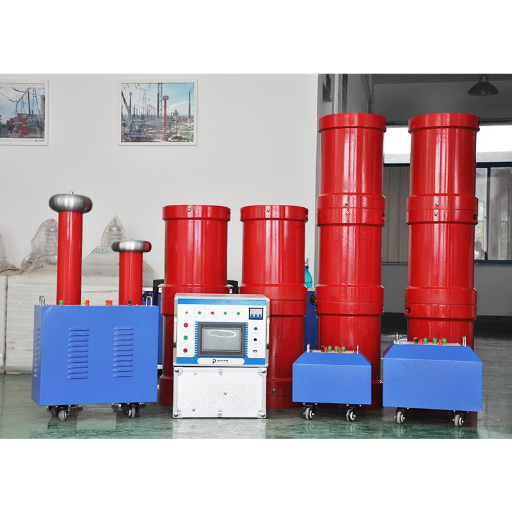
44–540 kVA
SPEC 017 standard DBP-DL complete systems (44 kV to 270 kV output; 400 kV, 1,600 kV modular cylinder cascades)
20–300 Hz
SPEC 02Variable frequency sweep with 0.1 Hz frequency resolution, plus 50 Hz / 60 Hz variable inductance sets
≤5 pC / <10 pC
SPEC 03Background partial discharge noise floor for PD-free cable systems and epoxy cylinder reactors
Q ≥ 30 (f=45 Hz)
SPEC 04High reactor quality factor lowers input power supply demand to active circuit losses
≤65 K (60 Min)
SPEC 05Continuous 60-minute full-load factory heat-run limit plus 1.1x overvoltage withstand for 1–3 minutes
15–30 Working Days
SPEC 06Standard manufacturing lead time, 1 set MOQ, T/T & L/C payment, and 24 hours engineer quote response
DEMIKS DBP-DL Series
US Patent US4338561A Architecture
Complete System Model Matrix (44 kVA to 540 kVA) and Sub-Component Specifications
Selecting a high voltage resonant test system requires matching both rated output voltage and capacitive charging current to the test object. A test system may have sufficient voltage capability for target kilovolts yet fail on a multi-kilometer power cable if its reactor current rating is undersized. Below are all 7 complete DBP-DL variable-frequency series resonant systems and 11 matched sub-components (variable-frequency power sources, excitation transformers, high-voltage reactors, and capacitive dividers) with an interactive model filter.
Series Resonant Tank Topology
Click stage to filter sub-components
44–540 kVA
Rated Capacity
22–270 kV
Output Voltage
20–300 Hz
Sweep Range
Q ≥ 30
Quality Factor
Showing 18 / 18
Interactive DBP-DL Model Selector & Sub-Component Matcher
Select target cable rated voltage class and route length to filter matching complete systems and sub-components.
Complete DBP-DL Systems (7 Models)
7 Models Displayed
Output Voltage Combinations
22 kV (parallel) / 44 kV (series)
Rated Current Stages
2 A / 1 A
Operating Frequency & Quality Factor
20–300 Hz, 0.1 Hz resolution, Q ≥ 30 (f=45 Hz)

Output Voltage Combinations
27 kV / 54 kV / 108 kV (four 27 kV reactors)
Rated Current Stages
4 A / 2 A / 1 A
Operating Frequency & Quality Factor
20–300 Hz, ≤1% waveform distortion, Q ≥ 30

Output Voltage Combinations
36 kV / 72 kV / 108 kV (three 36 kV reactors)
Rated Current Stages
3 A / 1.5 A / 1 A
Operating Frequency & Quality Factor
20–300 Hz, single reactor weight ≤120 kg, Q ≥ 30

Output Voltage Combinations
27 kV / 54 kV / 108 kV (high-current parallel/series)
Rated Current Stages
8 A / 4 A / 2 A
Operating Frequency & Quality Factor
20–300 Hz, RMS Class 1.5 accuracy, Q ≥ 30

Output Voltage Combinations
54 kV / 108 kV / 216 kV
Rated Current Stages
4 A / 2 A / 1 A
Operating Frequency & Quality Factor
20–300 Hz, 60-min rated thermal duty ≤65 K

Output Voltage Combinations
45 kV / 90 kV / 135 kV / 270 kV
Rated Current Stages
6 A / 3 A / 2 A / 1 A
Operating Frequency & Quality Factor
20–300 Hz, 220 V / 380 V input supply, Q ≥ 30

Output Voltage Combinations
45 kV / 90 kV / 135 kV / 270 kV (multi-unit cascade)
Rated Current Stages
12 A / 6 A / 4 A / 2 A
Operating Frequency & Quality Factor
20–300 Hz, ≤1% THD sine wave, Q ≥ 30 (f=45 Hz)
Sub-Component Specifications (11 Models)
11 Sub-Components Displayed
Sub-Component Model · Component Type: Variable-Frequency Power Source
DBP-DL-6kVA
Voltage & Current / Inductance / Capacitance
Input 220 V / 380 V; Output 0–400 V sine wave
Key Electrical & Mechanical Parameters
30–300 Hz (20–300 Hz sweep), ≤0.1 Hz resolution, 0.1% frequency stability documented in factory reports, 60-min heat rise ≤65 K

Sub-Component Model · Component Type: Variable-Frequency Power Source
DBP-DL-15kVA
Voltage & Current / Inductance / Capacitance
Input 220 V / 380 V; Output 0–400 V sine wave
Key Electrical & Mechanical Parameters
Embedded touch screen, automatic resonance tracking, over-voltage / over-current / flashover protection

Sub-Component Model · Component Type: Excitation Transformer
DLB-6kVA
Voltage & Current / Inductance / Capacitance
HV taps 1.5 kV / 3.0 kV / 6.0 kV
Key Electrical & Mechanical Parameters
Dry-type or oil-insulated, background partial discharge <5 pC, isolates LV inverter from HV resonant loop

Sub-Component Model · Component Type: Excitation Transformer
DLB-15kVA
Voltage & Current / Inductance / Capacitance
HV taps 2.5 kV / 5.0 kV / 10 kV / 15 kV
Key Electrical & Mechanical Parameters
60-minute continuous full-load temperature rise ≤65 K, Electrostatic inter-winding shield for PD suppression

Sub-Component Model · Component Type: Dry-Type Resonant Reactor
DDK-22kVA/22kV/100H
Voltage & Current / Inductance / Capacitance
22 kV rated voltage, 1 A current, 100 H inductance
Key Electrical & Mechanical Parameters
Cycloaliphatic epoxy resin casting, non-magnetic base, Q ≥ 30 at 45 Hz, single unit weight ≤120 kg
Sub-Component Model · Component Type: Dry-Type Resonant Reactor
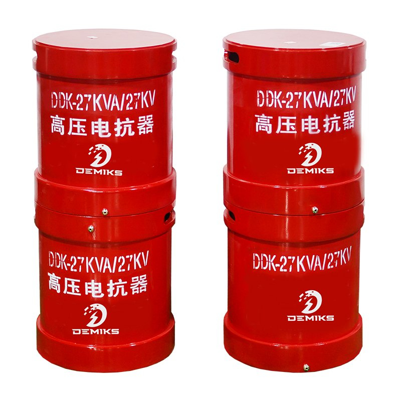
DDK-27kVA/27kV/100H
Voltage & Current / Inductance / Capacitance
27 kV rated voltage, 1 A current, 100 H inductance
Key Electrical & Mechanical Parameters
Stackable in series up to 108 kV or parallel up to 4 A; 60-minute continuous load temperature rise ≤65 K

Sub-Component Model · Component Type: Dry-Type Resonant Reactor
DDK-36kVA/36kV/100H
Voltage & Current / Inductance / Capacitance
36 kV rated voltage, 1 A current, 100 H inductance
Key Electrical & Mechanical Parameters
Designed for 35 kV cable and transformer AC withstand testing; background PD <10 pC at rated voltage

Sub-Component Model · Component Type: Dry-Type Resonant Reactor
DDK-54kVA/27kV/70H
Voltage & Current / Inductance / Capacitance
27 kV rated voltage, 2 A current, 70 H inductance
Key Electrical & Mechanical Parameters
High-current module for multi-kilometer XLPE cable commissioning; 1.1x overvoltage withstand for 3 minutes

Sub-Component Model · Component Type: Capacitive Voltage Divider
DFY-60kV/1000pF
Voltage & Current / Inductance / Capacitance
1,000 pF nominal capacitance
Key Electrical & Mechanical Parameters
Functions as both high-voltage divider and resonant compensation / coupling capacitor; dielectric loss <0.05% per the standard

Sub-Component Model · Component Type: Capacitive Voltage Divider
DFY-100kV/500pF
Voltage & Current / Inductance / Capacitance
500 pF nominal capacitance
Key Electrical & Mechanical Parameters
System voltage measurement accuracy ≤±1% (Class 1.5 effective system accuracy); coaxial shielded output lead

Sub-Component Model · Component Type: Capacitive Voltage Divider
DFY-110kV/1000pF
Voltage & Current / Inductance / Capacitance
1,000 pF nominal capacitance
Key Electrical & Mechanical Parameters
Cascadeable for 220 kV / 270 kV field AC withstand testing with double-ring corona grading shields
No models match the active filter combination.
Engineering Boundary: Output Voltage vs. Cable System Voltage Class:
The 7 standard DBP-DL complete models (44 kV to 270 kV maximum output voltage) directly cover field AC withstand testing up to 110 kV rated cable classes (where 2 U₀ equals 128 kV). Commissioning 220 kV cables (2 U₀ = 256 kV with margin) or 500 kV extra-high-voltage cables requires custom multi-unit reactor cascades up to 400 kV per single cylinder reactor or 1,600 kV in a four-unit cascade.
to filter configurations by cable length and voltage class.

Variable Frequency vs. Variable Inductance Architectures and Reactor Construction
Engineers procuring an AC resonant test system must first decide between two tuning principles: variable frequency series resonance (20–300 Hz) and variable inductance series resonance (50 Hz / 60 Hz). The movable air-gap core mechanism used in variable-inductance reactors follows the dual active core design in US Patent US8203412B2. They must also select between modular epoxy-glass cylinder reactors and grounded metal tank reactors based on whether the system operates in a mobile field trailer or a permanent factory test bay.
| Engineering Dimension | Variable Frequency Series Resonant System (DBP-DL Series) | Variable Inductance Resonant Test System (50 Hz / 60 Hz Series) |
|---|---|---|
| Resonance Tuning Mechanism | Fixed reactor inductance L (combined in series or parallel); variable-frequency converter sweeps 20–300 Hz (0.1 Hz resolution) per US4338561A principle | Fixed power frequency (50 Hz / 60 Hz or higher); rare-earth motor adjusts magnetic core air-gap distance to vary inductance L smoothly per US8203412B2 |
| Quality Factor (Q) & Input Power | Q ≥ 30 at 45 Hz under rated load; inverter supplies only active circuit losses (S_test / Q) | Q ranges from 10 to 100 depending on air-gap position; requires only 1/Q of test reactive power from mains regulator |
| Partial Discharge & Filter Design | Optical-fiber control isolation with ≤1% sine wave distortion; PD ≤5 pC with high-voltage blocking impedance filter | Low-voltage power filter plus high-voltage isolation impedance and coupling capacitor; pure 50/60 Hz sine wave ideal for IEC 60270 PD diagnostics |
| Module Weight & Field Mobility | Compact dry-cast or oil cylinder modules (single unit ≤120 kg for sets ≤108 kVA); ideal for substation vans and cable tunnels | Heavier motorized core mechanism; preferred for cable factories, type-test halls, and strict 50/60 Hz transformer or generator tests |
Modular Cylinder Type Resonant Reactor (Up to 400 kV Single / 1,600 kV Cascade)
DEMIKS modular cylinder reactors use an epoxy-reinforced glass-fiber insulating shell filled with transformer oil and fitted with an internal oil-resistant expansion diaphragm. A single insulating cylinder reactor can be rated up to 400 kV, and four units stacked in series reach 1,600 kV for extra-high-voltage laboratory and field testing. Double-ring corona sharing shields and a non-magnetic steel base allow fast assembly and disassembly for short-duration IEC withstand tests.
Grounded Metal Tank Type Resonant Reactor (Continuous Factory Duty)
For high-capacitance cable factories and continuous routine testing, DEMIKS supplies grounded metal tank reactors that can be placed directly next to laboratory walls or outdoors using a wall bushing. In variable-inductance metal tank designs, the excitation transformer can be built directly inside the grounded steel tank to save floor space. Metal tank reactors support continuous operation, multi-tap windings, and series connection on insulated pedestals.
Partial Discharge Noise Floor (≤5 pC vs. ≤10 pC) and Alternative HV Test Comparison
Data from more than 800 high-voltage XLPE cable circuits commissioned by Tecnalia Electrical Laboratories show that nearly 30% of field failures are caused by issues at joint and termination interfaces. As reported by INMR field diagnostics, nearly 80% of insulation defects in extruded power cables can be detected using partial discharge measurement per IEC 60270. A simple pass/fail test overvoltage hold.
| High-Voltage Test Technology | Operating Frequency & Waveform | Applicable Cable & Equipment Scope | Partial Discharge (PD) Compatibility | Power Supply & Weight Trade-Off |
|---|---|---|---|---|
| DEMIKS PD-Free AC Resonant Test System | 20–300 Hz (VF) or 50/60 Hz (VI), pure sine wave with ≤1% THD | 35 kV to 500 kV XLPE cables (IEC 60840, IEC 62067), GIS (IEC 62271-203), and HV transformers | Internal background noise ≤5 pC (PD-free cable sets) or <10 pC (dry cylinder reactors) for synchronous IEC 60270 PD measurement | Input power is only 1/30 to 1/50 of reactive kVA; modular units replace single 20-ton transformers |
| Power Frequency Test Transformer System | 50 Hz / 60 Hz mains sine wave | 6 kV to 110 kV short factory samples and routine insulator tests | Compatible with pulse-current PD detectors (0.1–10,000 pC, sensitivity ≤0.5 pC) in shielded halls | Requires 1:1 kVA power supply capacity; bulky oil-immersed tanks are impractical for long field cables |
| 0.1 Hz Very Low Frequency (VLF) Hipot | 0.1 Hz sinusoidal or cosine-rectangular wave (VLF test set) | 6 kV to 35 kV medium-voltage distribution cables per IEEE 400.2 | Supports VLF tan delta and PD location, unlike conventional hipot test equipment | Very compact HV testing equipment for MV maintenance, but not accepted as primary HV/EHV test in IEC 62067 |
| Damped AC (DAC) Voltage System | 20–500 Hz decaying oscillating wave (damped AC testing via HVDC charge) | Field diagnostic screening and PD localization per IEEE 400.4 | Effective for PD inception voltage (PDIV) and joint defect localization | Low input power, but applies decaying bursts rather than a continuous 60-minute IEC thermal/voltage soak |
| DC High-Voltage Generator (DC Hipot) | Direct current (ripple factor ≤1% to ≤5%) | HVDC submarine/land cables and legacy 6–35 kV auxiliary checks | Cannot replicate AC capacitive field grading or AC partial discharge phase patterns | Lightweight, but prohibited on service-aged AC XLPE cables by IEEE 400.1 due to destructive space-charge accumulation |