
Get in touch with DEMIKS Company

Multi-Channel Temperature Recorder & High-Current Thermocouple Data Logger Systems
This multi channel temperature recorder (also known as a multi channel temperature data logger, multi channel thermocouple data logger, temperature rise recorder, or thermocouple data recorder) allows each user to measure and record 16, 32, 48, or 64 sensor channels simultaneously during electrical heat-run verification and laboratory thermal profiling. DEMIKS offers the portable DWS-700 10-6 multi-channel thermo-hygrometer and temperature logger in addition to the DDL-WS 1,000 A to 10,000 A automatic temperature rise test system for switchgear, transformers, and power cable assemblies.
Contractual Response & Metrology Baseline:
Quotes and configuration proposals are returned within 6 hours, reviewed by a DEMIKS test engineer. Temperature channels hold ±1% temperature measurement accuracy (0–1370 °C imported K-type thermocouple) and 0.5-class current/voltage display across 1000–10000 A.
A modular 16-channel, 32-channel, 48-channel, and 64-channel Type K thermocouple input architecture
(expandable by user requirements) provides cold-junction compensation and strong-magnetic 50/60 Hz interference suppression, and enables simultaneous acquisition.
Closed-loop heat-run operation
links multichannel thermocouple recording directly to 0.5-class primary current regulation (1,000 A to 10,000 A maximum current), unlike a standalone benchtop data logger that only records temperature data while operators trim current by hand.
Pre-installed multi channel temperature recorder software and thermocouple data recorder software
on the dual RS485 industrial PC (plus internal memory on the paperless temperature recorder) let the user connect a USB flash drive to download CSV, Excel, and PDF reports.
At-a-Glance: Multi-Channel Temperature Data Logger & Heat-Run System Selection Summary
Industrial procurement teams and high-voltage test engineers regularly hit a specification trap when sourcing a multi-channel temperature data logger or high temperature data logger: catalog distributors group the $389 4-channel battery USB loggers with heavy-current switchgear temperature rise recorders. For high-current heat runs, recorder isolation and noise rejection affect temperature readings, and current regulation requires separate equipment or an integrated test system.
Core Measurement Capabilities & The High-Current Loop-Immunity Guide
Engineering a reliable multichannel temperature acquisition architecture inside a high-voltage test bay requires solving a fundamental physics challenge: a Type K thermocouple generates approximately 41 µV/°C near 25 °C (~51 mV at 1,250 °C), yet it must measure and sample temperatures millimeters away from copper busbars carrying 1,000 A to 10,000 A at 50 Hz or 60 Hz [7]. On Reddit engineering forums, test engineers repeatedly struggle with “periodic 50/60 Hz magnetic noise spikes on thermocouple leads” that corrupt readings the instant the primary current transformer energizes.
As unshielded thermocouple loops act as single-turn secondary windings in strong alternating magnetic fields, relying on an unshielded USB temperature data logger is the wrong decision for switchgear or transformer heat runs. DEMIKS engineers each DDL-WS system around cold-junction compensation, strong-magnetic field anti-interference design, and isolated RS485 digital transmission between the high-current upflow unit and the operator console.
Calculate Your Exact Thermocouple Uncertainty Before You Specify: Not always does 0.1 °C display resolution mean 0.1 °C measurement accuracy. Open our Interactive Type K Thermocouple & Cold-Junction Error Budget Calculator to model probe tolerance, CJC block stability, ADC linearity, and residual noise at your target test temperature.
±1.51 °C RSS
Probe ±1.50°C | CJC ±0.05K
Thermocouple Sensor Types, Probe Sheath Materials & Signal Compatibility
Choosing the right temperature sensor probe and insulation assembly is just as critical as choosing the thermocouple data logger. While RTD (Pt100) and thermistor probes serve narrow ambient or laboratory freezer monitoring applications, industrial switchgear, transformer, and cable thermal cycling tests rely on k-type thermocouple (Chromel/Alumel, 0 °C to 1,370 °C wide span) and j-type thermocouple probes (specified separately by temperature range) because of their fast thermal response and compact tip geometry.
MgO Moisture Contamination & Sheath Exposure
There are two primary issues at the material level in multipoint temperature campaigns that are particularly concerning to practitioners; the first is the concern of “MgO moisture contamination causing negative thermocouple drift.” Hygroscopic MgO insulation in unsealed mineral-insulated probes absorbs shop-floor humidity; as reported in Control Engineering, moisture contamination lowers insulation resistance and can create negative Drift EMF so the instrument reads cooler than the actual busbar temperature [4]. In its tested configuration, the Sensors (Basel) study (PMC8512746) reported that exposing the metallic sheath reduced the RSF by more than 60% [3].
> 60% RSF
Reduction reported when exposing metallic sheath (PMC8512746) [3]
Negative EMF
Hygroscopic MgO moisture lowers insulation resistance [4]
Ambient & Humidity Data Correlation
For laboratories requiring combined temperature and humidity validation, the portable DWS-700 10-6 (-40 °C to +120 °C, 0–100% RH, 0.01 °C / 0.01% RH resolution) records room environment humidity alongside DDL-WS thermocouple data so every PDF and Excel report documents ambient conditions clearly.
-40 °C to +120 °C
DWS-700 10-6 span with 0.01 °C resolution
0–100% RH
0.01% RH synchronized PDF & Excel logging
Table 3: Compatible Sensor Inputs, Probe Materials & Application Envelope
| Sensor / Input Type | Temperature Range & Tolerance Standard | Recommended Sheath & Lead Specification | Primary Electrical Testing Use Case |
|---|---|---|---|
| Imported Type K Thermocouple (Standard on DDL-WS) | 0 °C to 1,370 °C wide range (0 °C to 260 °C heat-run module) per IEC 60584-1:2013 and ASTM E230 (±2.2 °C or ±0.75% Standard; ±1.1 °C or ±0.4% Special Limits) [2], [7]. |
Metallic sheath or fiberglass/PTFE twisted-pair lead with < 100 Ω recommended loop resistance (1,000 Ω maximum per industry baseline) [6]. |
Switchgear contacts, copper busbar joints, dry-type transformer cores, and cable conductor heat runs. |
| Type J / Type T Thermocouple Probes (Configurable Input) | Specified separately by wire type and temperature span under ASTM E230 and IEC 60584-1 tolerance classes [2]. |
FEP/PTFE insulated twisted pair with exposed or ungrounded junction tip. | Enclosure surface temperature rise, secondary wiring bundles, and ambient reference channels. |
| Pt100 RTD & Thermistor Reference Sensors (DWS-700 & CJC) | -40 °C to +120 °C (±0.3 °C at 25 °C on DWS-700 10-6); ±0.05 K (PR103J2) to ±0.18 °F (AMS2750H) CJC thermistor tracking [3]. |
7 m sensor probe cable (DWS-700 10-6) or silicone-oil thermal buffer cylinder for ambient air channels. |
Reference ambient air temperature and 0–100% RH humidity monitoring (1 m from enclosure per IEC 62271-1). |
| Analog DC Voltage, DC Current & Pulse Channels | ±80 mV thermocouple millivolt input span [7], plus 0.2 class current transformer and 0.5-class voltage/current display channels, DC current, and pulse inputs. |
Shielded instrumentation cable coupled to the DEMIKS primary current transducer interface. | Synchronizing primary injection current (1,000–10,000 A), voltage drop, humidity data, and pulse signals with temperature logs. |
Isothermal Cold-Junction Compensation, Enclosure Shielding & Interface Architecture
A common myth in instrumentation procurement is that calibrating the thermocouple wire guarantees ±0.5 °C multi-channel accuracy. Thermoelectric voltage occurs along the temperature gradients in the thermocouple circuit, and cold-junction compensation error, affects the temperatures calculated using that reference. Engineers on test benches, routinely experience “screw-terminal thermal gradients across multi-channel input blocks” when internal power supplies or rack fans, warm one side of a 16-channel or 20-channel plug-in card.
“Testing a 20-channel multiplexer module with built-in screw-terminal cold-junction compensation revealed up to 0.8 K absolute CJC error and a 0.4 K temperature gradient across the 20 screw terminals after 12 hours on a lab bench, and up to 2.0 K error inside an instrument rack, whereas an external 80 × 40 × 15 mm³ passive isothermal aluminum block reduced reference-junction error to 0.01–0.05 K.”
Lundström & Mattsson, Sensors (Basel), PMC8512746 (Peer-Reviewed Metrology Study) [3]
In addition, verified buyer reviews on commercial benchtop data loggers highlight another field failure: “proprietary PC software lock-in and lost serial keys” that turn a $3,000 instrument into a paperweight when a CD license key is misplaced or when Windows-only software corrupts multi-day CSV and Excel timestamp exports. That’s hardware gradient drift and software lock-in. Industrial hardware shielding and data open dual-mode export eliminate both.
'/%3E%3Crect width='900' height='640' fill='url(%23glow)'/%3E%3Cg stroke='%23F0A830' stroke-opacity='0.28' stroke-width='1.5' fill='none'%3E%3Crect x='54' y='54' width='792' height='532'/%3E%3Cline x1='54' y1='187' x2='846' y2='187'/%3E%3Cline x1='54' y1='320' x2='846' y2='320'/%3E%3Cline x1='54' y1='453' x2='846' y2='453'/%3E%3Ccircle cx='740' cy='120' r='34'/%3E%3Ccircle cx='740' cy='253' r='34'/%3E%3Ccircle cx='740' cy='386' r='34'/%3E%3Ccircle cx='740' cy='519' r='34'/%3E%3C/g%3E%3C/svg%3E)
Multi-Channel Recorder and 8-Model DDL-WS Specification Matrix
We size configurations from your test object type, rated current, thermocouple channel count, and target test standard. The temperature channels hold ±1% temperature measurement accuracy (0–1370 °C imported K-type thermocouple) and 0.5-class current/voltage display across 1000–10000 A. Whether you need a portable 1.5 kg logger (DWS-700 10-6) or a 16-to-64-channel automatic temperature rise test system (DDL-WS), the master specification matrix below maps all 8 DEMIKS models side by side.
Table 4: Master 8-Model Specification Matrix — DWS-700 10-6 & DDL-WS Automatic Temperature Rise Series

DWS-700 10-6
Portable Handheld Multi-Channel Thermo-Hygrometer & Logger (7 m probe cable, lithium battery + USB).
Rated Output Current & Voltage: Standalone logger (no current injector; 10 h continuous battery runtime).
- Rated Capacity & Power Supply: Internal Li-ion battery + AC 220 V ±10%, 50 Hz charger (60 Hz adapter available).
- Standard Channels & Sensor Range: -40 °C to +120 °C & 0–100% RH (customizable Type K -20 °C to 1,000 °C module).
- Accuracy & Display Resolution: ±0.3 °C (25 °C), ±2% RH, 0.01 °C / 0.01% RH res. (±0.5% + 1 °C, 0.1 °C on Type K).
- Upflow Unit Dimensions & Weight: Portable handheld device · ~1.5 kg weight.

DDL-WS-1000A
Single-Phase Automatic Temperature Rise Test System (Console + Upflow).
Rated Output Current & Voltage: 1,000 A AC (6 V output voltage).
- Rated Capacity & Power Supply: 6 kVA · Input AC 380 V ±10%, 50 Hz (60 Hz custom option).
- Standard Channels & Sensor Range: 16 channels standard (expandable); Imported Type K 0–1,370 °C (0–260 °C heat-run module).
- Accuracy & Display Resolution: ±1% temp accuracy (±0.5% + 1 °C heat-run module, 0.1 °C res.) · 0.5-class V/I · 0.5% current stability.
- Upflow Unit Dimensions & Weight: Console: 1400 × 800 × 900 mm (90 kg) · Upflow: 400 × 550 × 800 mm (100 kg).

DDL-WS-1000S
Three-Phase Automatic Temperature Rise Test System (Sync 3-Phase Regulation).
Rated Output Current & Voltage: 1,000 A AC per phase (5 V output voltage).
- Rated Capacity & Power Supply: 15 kVA · Input AC 380 V ±10%, 50 Hz (60 Hz custom option).
- Standard Channels & Sensor Range: 48 channels standard (16–48 ch modular); Imported Type K 0–1,370 °C.
- Accuracy & Display Resolution: ±1% temp accuracy (0.1 °C res.) · 0.5-class V/I display · 0.5% current stability.
- Upflow Unit Dimensions & Weight: Console: 1600 × 800 × 900 mm (120 kg) · Regulator: 150 kg · Upflow: 160 kg.

DDL-WS-1500A
Single-Phase Automatic Temperature Rise Test System.
Rated Output Current & Voltage: 1,500 A AC (6 V output voltage).
- Rated Capacity & Power Supply: 10 kVA · Input AC 380 V ±10%, 50 Hz (60 Hz custom option).
- Standard Channels & Sensor Range: 16 channels standard (16–32 ch modular); Imported Type K 0–1,370 °C.
- Accuracy & Display Resolution: ±1% temp accuracy (0.1 °C res.) · 0.5-class V/I display · 0.5% current stability.
- Upflow Unit Dimensions & Weight: Console: 1400 × 800 × 900 mm (90 kg) · Upflow: 450 × 550 × 900 mm (130 kg).

DDL-WS-4000S
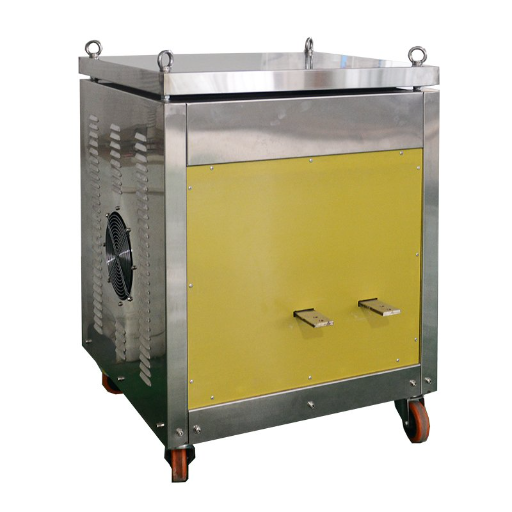
Three-Phase High-Current Temperature Rise Test System (Forced Air Cooled).
Rated Output Current & Voltage: 4,000 A AC per phase (10 V output voltage).
- Rated Capacity & Power Supply: 120 kVA · Three-phase four-wire AC 380 V ±10%, 50 Hz (60 Hz custom).
- Standard Channels & Sensor Range: 64 channels standard (24–64 ch expandable); Imported Type K 0–1,370 °C.
- Accuracy & Display Resolution: ±1% temp accuracy (0.1 °C res.) · 0.5-class V/I display · 0.5% current stability.
- Upflow Unit Dimensions & Weight: Console: 1600 × 800 × 900 mm (120 kg) · Reg: 650 kg · Upflow: 1150 × 650 × 1200 mm (700 kg).

DDL-WS-5000A
Single-Phase Heavy-Current Temperature Rise Test System.
Rated Output Current & Voltage: 5,000 A AC (6 V output voltage).
- Rated Capacity & Power Supply: 30 kVA · Input AC 380 V ±10%, 50 Hz (60 Hz custom option).
- Standard Channels & Sensor Range: 32 channels standard (expandable); Imported Type K 0–1,370 °C.
- Accuracy & Display Resolution: ±1% temp accuracy (0.1 °C res.) · 0.5-class V/I display · 0.5% current stability.
- Upflow Unit Dimensions & Weight: Console: 1400 × 800 × 900 mm (90 kg) · Reg: 200 kg · Upflow: 500 × 700 × 900 mm (220 kg).

DDL-WS-6000A
Single-Phase Heavy-Current Temperature Rise Test System.
Rated Output Current & Voltage: 6,000 A AC (8 V output voltage).
- Rated Capacity & Power Supply: 50 kVA · Input AC 380 V ±10%, 50 Hz (60 Hz custom option).
- Standard Channels & Sensor Range: 32 channels standard (32–48 ch expandable); Imported Type K 0–1,370 °C.
- Accuracy & Display Resolution: ±1% temp accuracy (0.1 °C res.) · 0.5-class V/I display · 0.5% current stability.
- Upflow Unit Dimensions & Weight: Console: 1400 × 800 × 900 mm (90 kg) · Reg: 300 kg · Upflow: 650 × 750 × 1000 mm (320 kg).

DDL-WS-10000S
Three-Phase Ultra-High-Current Temperature Rise System (Dual-Split Upflow).
Rated Output Current & Voltage: 10,000 A AC per phase (15 V output voltage).
- Rated Capacity & Power Supply: 450 kVA · Three-phase AC 380 V ±10%, 50 Hz (60 Hz custom).
- Standard Channels & Sensor Range: 64 channels standard (expandable per user requirements); Imported Type K 0–1,370 °C.
- Accuracy & Display Resolution: ±1% temp accuracy (0.1 °C res.) · 0.5-class V/I display · 0.5% current stability.
- Upflow Unit Dimensions & Weight: Console: 1600 × 800 × 900 mm (120 kg) · Reg (×2): 1100 kg each · Upflow (×2): 1150 kg each.
Switchgear Heat-Run Channel Budgeting Schedule (IEC 62271-1 & IEC 61439-1)
A 20% to 25% spare-channel allowance provides capacity for additional hot-spot measurements when sizing a 16 channel thermocouple data logger or a 32-, 48-, or 64-channel temperature rise recorder; probe changes that require opening a busbar connection are made after the test circuit is de-energized [5]. Use the schedule below or launch our Interactive Switchgear & Transformer Heat-Run Channel Count Planner to calculate your terminal count.
Test Object Class
Single-Phase Breaker, Fuse Disconnector, or Cable Loop (≤ 1,500 A)
Active Measurement Points
6 to 10 channels (inlet/outlet terminals, contact bridge, cable lug, housing).
Ambient Air Sensors
3 ambient channels.
20–25% Spare Allowance
3 spare channels.
Recommended DEMIKS Model by Current & Channel Tier
16-Channel Tier: DDL-WS-1000A (up to 1,000 A) or DDL-WS-1500A (up to 1,500 A).
Test Object Class
Three-Phase MV/LV Switchgear Panel (1,000 A to 4,000 A)
Active Measurement Points
18 to 22 channels (3 phases × upper/lower breaker contacts, busbar splice, CT joint, cable head + enclosure doors).
Ambient Air Sensors
4 ambient channels (1 m distance).
20–25% Spare Allowance
For a three-phase switchgear panel with 18 to 22 active points, four ambient channels, and six spare channels, use a 32-channel configuration: DDL-WS-1000S for tests up to 1,000 A or DDL-WS-4000S for tests up to 4,000 A.
Recommended DEMIKS Model by Current & Channel Tier
32-to-64-Channel Tier: DDL-WS-1000S (48 ch, for tests up to 1,000 A) or DDL-WS-4000S (64 ch, for tests up to 4,000 A).
Test Object Class
Heavy Single-Phase Busway or Three-Phase Generator Breaker (5,000 A to 10,000 A)
Active Measurement Points
24 to 48 channels (parallel busbar laminations, phase enclosures, top-oil, cooling fins, flexible shunts).
Ambient Air Sensors
4 ambient channels.
20–25% Spare Allowance
8 to 12 spare channels.
Recommended DEMIKS Model by Current & Channel Tier
High-Current Tier: For a 64-channel, 10,000 A three-phase heat run, select DDL-WS-10000S; single-phase DDL-WS-5000A and DDL-WS-6000A provide 32 channels standard (expandable).
Frequently Asked Questions: Multi-Channel Temperature Recorders & Heat-Run Systems
How many thermocouple channels should we specify for a three-phase switchgear heat-run test?
For the proposed three-phase switchgear layout, 18 to 22 active Type K measurement points across phases A, B, and C (upper and lower breaker contacts, busbar splices, current transformer joints, cable lugs, and enclosure doors) plus 3 to 4 ambient air sensors (1 m away per IEC 62271-1) require 21 to 26 inputs before adding a 20% to 25% spare-channel allowance; busbar connections are changed only after the test circuit is de-energized [5]. Depending on your rated test current, select the 48-channel DDL-WS-1000S (up to 1,000 A) or the 64-channel DDL-WS-4000S (up to 4,000 A), or size your layout in our Heat-Run Channel Count Planner.
How does the recorder suppress 50/60 Hz magnetic noise near 1,000 A to 10,000 A busbars?
Every DEMIKS DDL-WS recorder combines cold-junction compensation (CJC), strong-magnetic field anti-interference shielding (0.1 °C resolution, ±0.5% + 1 °C heat-run module accuracy), and isolated dual-RS485 communication that separates the operator console from the 1,000 A to 10,000 A upflow generator.
What are your delivery lead times, payment terms, warranty, and overseas commissioning options?
Standard DWS-700 and DDL-WS setups ship within 25 days after order confirmation, and custom multi-channel and high-current temperature rise systems ship in 45 days after specification sign-off. Orders settle via T/T wire transfer under EXW, FOB Shanghai, or CIF Incoterms, backed by a 12-month warranty and on-site overseas engineer installation, commissioning, and operator training.
What third-party calibration certificates are included with shipment?
Pre-shipment inspection is submitted to a CMA and CNAS accredited third-party testing institution for formal test reports. A third-party CMA/CNAS inspection report and English operating documentation ship with your order, recording the verified test results for your delivered system.
How does the ±1% system accuracy relate to probe error and cold-junction compensation?
Temperature channels hold ±1% temperature measurement accuracy (0–1370 °C imported K-type thermocouple) and 0.5-class current/voltage display across 1000–10000 A. At 200 °C, the worked ±1.25 °C root-sum-square (RSS) budget on sciotex.com combines the ASTM E230 Special Limits Type K wire contribution (±1.1 °C), cold-junction error (±0.5 °C), ADC error (±0.3 °C), and residual electrical noise (±0.05 °C); this illustrative calculation shows component interactions, while pre-shipment third-party metrology testing evaluates your ordered DEMIKS system against its rated accuracy [7].
Does the PC software require paid annual licenses or proprietary serial keys?
Nope; the pre-installed Windows 10/11 heat-run software and 64 MB+ internal memory export directly to USB, CSV, Excel, and PDF with no license fees.
Can DEMIKS systems operate on 60 Hz power grids in North and South America?
Yes; while standard domestic units use AC 380 V ±10%, 50 Hz, we build custom 60 Hz (220 V / 380 V / 480 V) systems for North and South America in 45 days.
Can we buy a portable logger without the high-current generator?
Yes, order the 1.5 kg handheld DWS-700 10-6 (-40 °C to +120 °C, ±0.3 °C, 2 units MOQ) whenever you do not need primary current injection.
Include five parameters in your RFQ:
01
test object type (switchgear, breaker, liquid-immersed or dry-type transformer, cable),
02
rated test current (1,000 A, 10,000 A for the DDL-WS series, or a standalone logger),
03
required thermocouple channel count (16, 32, 48, or 64 channels),
04
target test standard (IEC 62271-1, IEC 60947-1, IEC 61439-1, IEC 60076-2, or IEC 60076-11), and
05
facility grid supply (50 Hz or 60 Hz).
Check out our self-service engineering tools with no email gate:
open the Interactive 8-Model & Channel Selector, run the Type K Thermocouple & CJC Error Budget Calculator, or size your bay with the Switchgear & Transformer Heat-Run Channel Planner.
Request a 6-Hour Multi-Channel Temperature Recorder & Heat-Run System Quote
Ready to specify a portable DWS-700 10-6 multi-channel logger or a turnkey DDL-WS (1,000 A to 10,000 A) automatic temperature rise test system? Quotes and configuration proposals are returned within 6 hours, reviewed by a DEMIKS test engineer.
Contact our engineering desk directly
via email at contact@demikspower.com or WhatsApp / Phone at +86 13916614261 (Lingang Special Area, China (Shanghai) Pilot Free Trade Zone, Shanghai, China).