Temperature Rise Test System for Switchgear, Breakers & Busbars

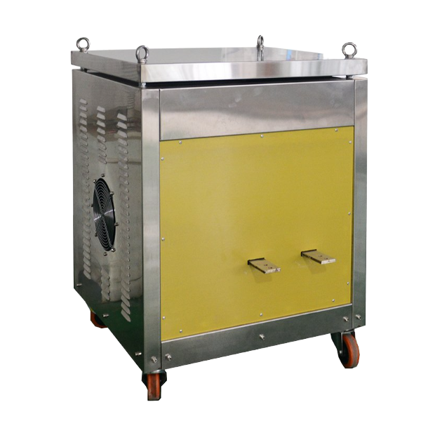
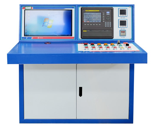
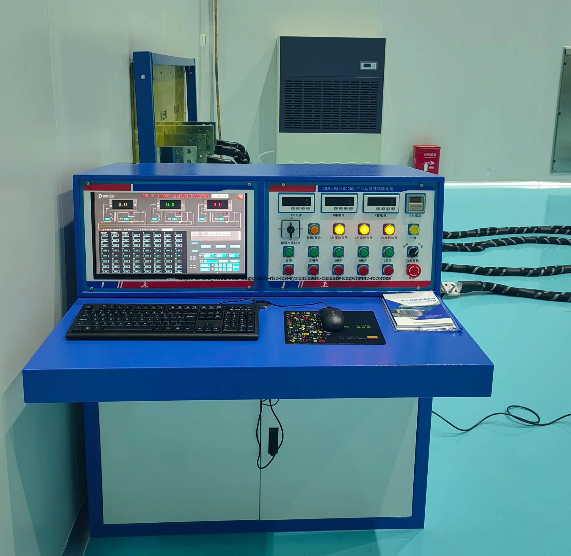
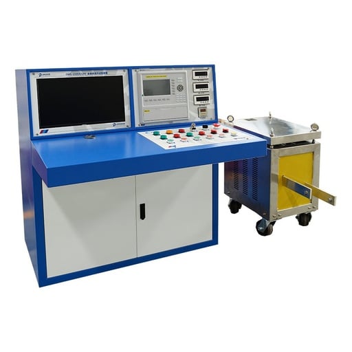
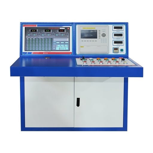
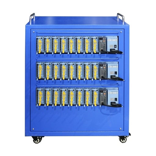
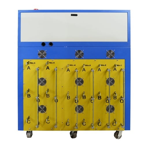
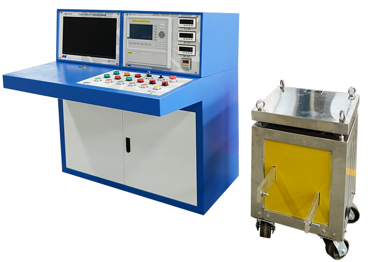
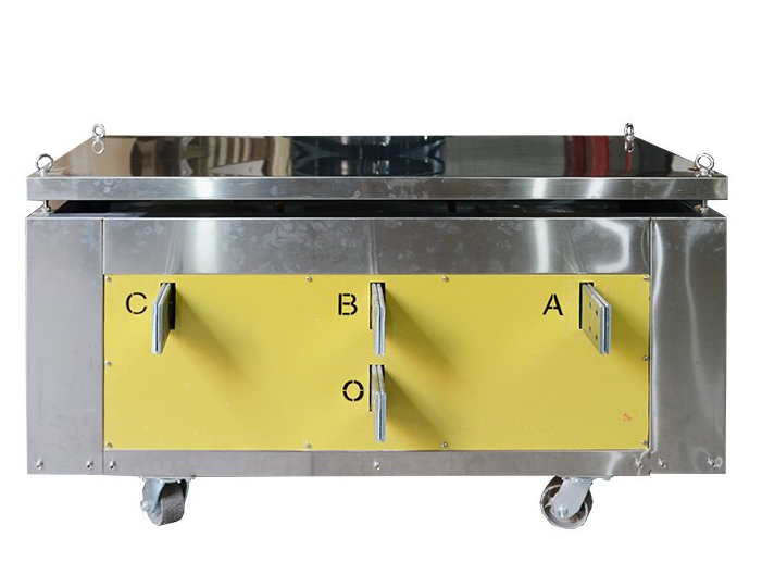
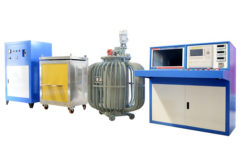
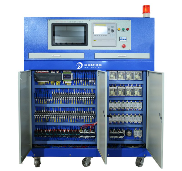
DEMIKS has developed Automated temperature rise test systems that allow for continuous primary current injection up to 10,000A. These systems are engineered to perform under the most stringent thermal loading conditions. Heavy-duty oil-immersed induction voltage regulators and multi-channel 4-wire Pt100 thermal logging provide verified compliance to IEC 62271-1, IEC 61439-1, and IEC 60947-1, without issues like carbon brush wear or electromagnetic noise drift.

Temperature Rise Test System for Switchgear, Breakers and Busbars
  • 1,000A, 10,000A

    Continuous AC Primary Injection Output

  • ≤ 3.0%

    Low Output Waveform Distortion (THD)

  • ± 0.5 °C

    4-Wire Pt100 Acquisition Accuracy

  • ≤ 1 K/h

    Automated Thermal Steady-State Shutdown

Critical Bottlenecks in High-Current Heat Run Testing

Temperature rise testing is the final thermal qualification test for power transmission and distribution equipment. High-voltage gas-insulated switchgear (GIS) equipment, medium-voltage air-insulated switchgear (AIS) equipment, low-voltage switchboard assemblies, busbar trunking systems and power transformers must carry their rated normal currents continuously without exceeding standard temperature rise limits. During the testing, laboratories and electrical manufacturers usually experience serious operational bottlenecks with the conventional heat run tests.

  • Carbon Brush Arcing and Thermal Breakdown in High-Current Heat Run Testing
    01

    Carbon Brush Arcing and Thermal Breakdown

    Traditional primary injection sets employ contact autotransformers (Variacs) with carbon brush sliders. When driving continuous currents above 3,000A for 8 to 24 hours, contact friction and localized overheating cause severe brush pitting, arcing, and sudden voltage drop, forcing test aborts and specimen re-cooling.

  • 02

    Electromagnetic Noise Distorting Thermal Curves

    Thousands of amperes generates significant stray alternating magnetic fields. Standard thermocouple sensors deployed inside switchgear compartments are subject to magnetic induction loops, EMI and reference junction drift, giving false temperature spikes of 3°C to 8°C.

  • Manual Steady-State Misjudgment in High-Current Heat Run Testing
    03

    Manual Steady-State Misjudgment

    According to IEC 62271-1 and IEC 61439-1, the heat run must continue until the rate of temperature rise does not exceed 1 K per hour. Manually logging thermometer readings across 32 or 64 channels is time-consuming, error-prone and invites either a premature shutdown or unnecessary waste of energy.

These testing failure points are eliminated because our automated temperature rise test benches incorporate heavy-duty induction voltage regulation and multi-channel isolated platinum resistance data acquisition.

System Configuration Inquiry

Physics of Continuous Primary Injection and Thermal Drift

The source of the heat generated in electrical switchgear is resistive losses (P = I²R) along the main busbars, disconnect blade contacts, circuit breaker tulip contacts, drawout socket jaws, high-current connector links, and cable connection terminals. As conductors heat up, the resistivity of copper increases according to ρT = ρ20 × [1 + α(T - 20)], where α = 0.00393 / K. With a 60 K temperature increase, the resistance of electrical increases by approximately 23.6%, resulting in an increase of the load impedance of the primary injection loop during testing.

DDL-WS Technical Configuration Inquiry
Physics of Continuous Primary Injection and Thermal Drift

Sagging current is a problem if the primary injection source operates in an open loop or motor-driven carbon brushes. The test current decays as bus bars heat up. A 5% drop in test current results in a 9.75% reduction in Joule heating power (heating power proportional to I²), corrupting thermal equilibrium data and invalidating type test certification under IEC 62271-1.

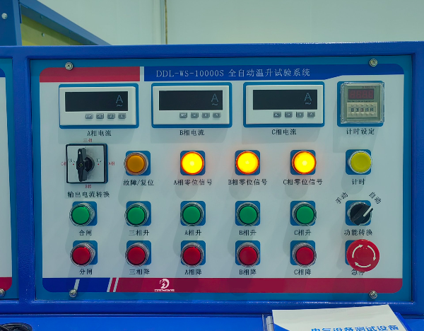
Our DDL-WS series incorporates continuous closed-loop current feedback controlled by programmable logic controllers (PLCs). This ensures precise regulation of loop current over long periods of time. The system continuously samples real-time loop current via precision class 0.2 current transformers, executing smooth voltage micro-adjustments within 50 milliseconds to keep output current stable within ±0.5% throughout 24-hour heat runs.

Oil-Immersed Induction Voltage Regulation vs Sliding Carbon Brushes

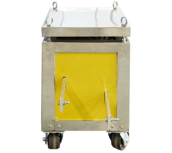
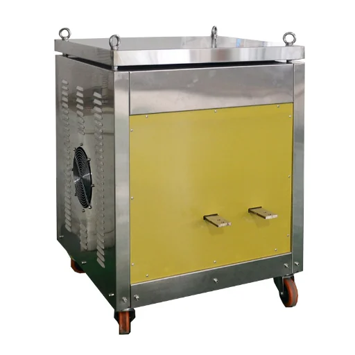
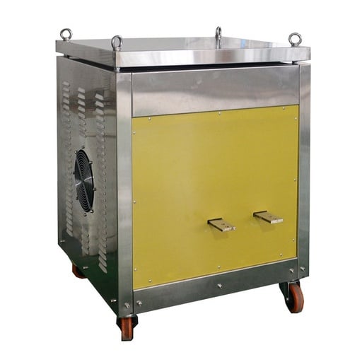
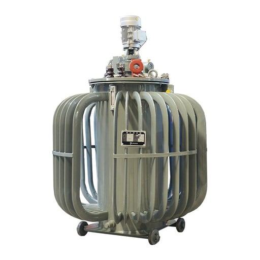
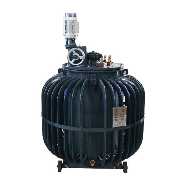
To maintain continuous testing under IEC 62271-1, the core regulator is the most essential reliability element in any of our temperature rise test equipment. We strictly prohibit the use of Dry-type sliding carbon brush Variacs in our high current systems. We standardize on heavy-duty Oil-Immersed Induction Voltage Regulators (IVR) in these systems. Carbon brush variacs are not interchangeable with induction regulators; saving capital on carbon brushes costs you continuous maintenance and downtime, making the engineering trade-off clear. Cheap slide-wire designs do nothing for heavy duty cycles.

Oil-Immersed Induction Voltage Regulation vs Sliding Carbon Brushes
Engineering Parameter DEMIKS Oil-Immersed Induction Regulator (IVR) Conventional Contact Variac (Carbon Brush)
Regulation Mechanism Electromagnetic induction via rotor angular rotation; zero sliding contacts Mechanical friction carbon brush sliding directly on exposed copper windings
Continuous Duty Cycle 100% continuous duty rating at full rated load for 24+ hours Limited continuous duty; carbon brushes overheat after 4 to 6 hours
Mechanical Wear & Pitting Zero wear parts; immersed in transformer insulation oil Frequent brush replacement, contact surface pitting, and copper grooving
Waveform Distortion (THD) Sinusoidal output with total harmonic distortion ≤ 3.0% Harmonic distortion often exceeds 5.0% due to brush contact resistance nonlinearity
Cooling & Environmental Protection Sealed oil tank cooling (ONAN); immune to dust, humidity, and chemical vapors Air-cooled open frame; highly susceptible to ambient industrial dust and moisture
Service Life Expectancy Exceeds 20 years with periodic oil dielectric testing Requires carbon brush replacement every 300 to 500 running hours

By rotating a cylindrical wound rotor within a stator core, our induction regulator smoothly alters magnetic flux coupling to deliver stepless, spark-free voltage regulation from 0V to maximum output. Because our regulator produces a spark-free variation of magnetic flux coupling, it produces a smoother transition from 0V to maximum output than mechanical regulators. The voltage regulator provides fundamental sinusoidal current waveforms necessary for electromagnetic verifications according to the IEC standards.

High-Precision 4-Wire Pt100 Acquisition in High-Magnetic Fields

AccuTuro Zen temperature monitoring employs sensors and signal conditioning devices that are resistant to high-density magnetic flux. In a 5,000A busbar loop, stray magnetic fields can exceed 15 milliteslas, which creates significant common-mode and normal-mode noise voltages in sensor wiring. DEMIKS engineers resolve this instrumentation challenge because thermocouples do nothing for heavy electromagnetic noise immunity, whereas four-wire Pt100 RTDs provide reliable common-mode rejection with NIST traceable calibration in demanding OEM switchgear testing applications on the bench.

Industrial 4-Wire Pt100 RTD Configuration

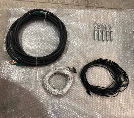
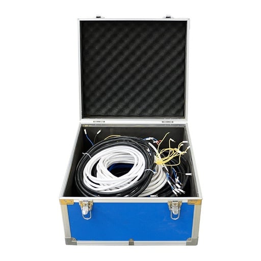
A DWS-700 multi-channel temperature recorder uses industrial Class A 4-wire Pt100 resistance temperature detectors (RTDs). Two leads supply a stable 1mA excitation current, while the other two leads measure the voltage drop directly across the platinum resistor. Lead wire resistance and temperature gradients along the test cable bundle are completely eliminated.

Channel-to-Channel Galvanic Isolation

Each measurement channel features 1,500V RMS galvanic isolation and differential delta-sigma analog-to-digital conversion. When used with 1,500V RMS galvanic isolated sensor probes, dangerous ground loops across long switchgear lines and potential test instrumentation damage are eliminated.

High-Precision 4-Wire Pt100 Acquisition in High-Magnetic Fields

Our measurement system achieves an absolute temperature accuracy of ±0.5°C with a display resolution of 0.1°C across a measurement range of -50°C to +200°C. Data logging intervals are user-configurable from 1 second to 60 minutes, with real-time temperature curves plotted dynamically across all active channels.

  • Accuracy ±0.5°C
  • Resolution 0.1°C
  • Temp Range -50°C to +200°C
  • Isolation 1,500V RMS
  • Flux Immunity >15 mT (5,000A)
  • Log Interval 1s – 60min

Automated Thermal Equilibrium Detection under IEC 62271-1 and IEC 61439-1

"A temperature rise test is considered complete when the rate of temperature rise at all monitored measurement points does not exceed 1 K per hour over a continuous observation period."

— IEC 62271-1 Standard Definition

The international standards IEC 62271-1 (High-Voltage Switchgear and Controlgear), IEC 61439-1 (Low-Voltage Switchgear and Controlgear Assemblies), and IEC 60947-1 (Low-Voltage Switchgear and Controlgear Appliance Testing) give exact mathematical ways to determine when a test specimen has attained thermal steady state.

The heat run test will continue until the temperatures stabilize at the monitored points. The steady state is considered to be reached when the temperature rise does not increase by more than 1 K per hour over a consecutive observation interval of one to two hours. This will also be considered stable if the temperature rise averages 0.5 K for a 2 hour period.

Our supervisory control software automates this determination by continuous regression analysis:

  • Moving-Average Slope Estimation:

    The software continues to calculate the thermal rate of change (dT/dt) for every individual sensor channel over 60 minute rolling windows.

  • Automated Steady-State Detection:

    When all of the critical monitored locations satisfy dT/dt ≤ 1 K/h, the system will generate an audible signal and records the final equilibrium temperatures. The system also executes an automated safe ramp down of the primary current.

  • Hot Resistance Extrapolation:

    The system supports immediate 4-terminal DC resistance measurement of electrical coils and transformer windings to calculate average internal winding temperatures via the resistance method.

  • Full Traceable Test Reporting:

    On completion of a test the system generates detailed test records containing channel assignment tables, peak temperature logs, ambient temperature curves, and standard compliance pass/fail assessments which are exportable to PDF and Excel.

Automated Thermal Equilibrium Detection under IEC 62271-1 and IEC 61439-1

Normative Temperature Rise Limits and Verification Matrix

Diverse joint plating technologies and insulating media are rated for maximum allowable temperature rises. Our test benches are designed to monitor these, compare them to the threshold values, and perform an automated benchmarking function against them.

Component / Material Type Applicable Standard Max. Permissible Temperature Rise (ΔT) Max. Absolute Operating Temperature
01 Bare Copper Busbars & Conductors
IEC 62271-1 / GB/T 11022 60 K 100 °C
02 Silver-Plated or Nickel-Plated Contacts
IEC 62271-1 / IEC 61439-1 75 K 115 °C
03 Tin-Plated Bolted Joints & Terminals
IEC 62271-1 / IEC 60947-1 65 K 105 °C
04 External Cable Connection Terminals
IEC 61439-1 Clause 10.10 70 K 110 °C
05 Operating Handles & Manual Controls (Metallic)
IEC 62271-1 / IEC 61439-1 30 K 70 °C
06 Enclosure External Accessible Surfaces
IEC 62271-1 / IEC 61439-1 30 K (Metallic) / 40 K (Insulating) 70 °C / 80 °C
07 Liquid-Immersed Transformers (Top Oil / Windings)
IEC 60076-2 Clause 7 60 K (Top Oil) / 65 K (Winding Average) 100 °C / 105 °C

Note: Temperature rise is relative to the ambient air or cooling medium temperature measured during the test. The 40°C threshold represents a reference condition for standardized service rather than a fixed test baseline.

Custom System Configurations: 1,000A to 10,000A Capacities

In compliance with IEC 62271-1, each temperature rise test system is engineered to specific requirements of testing capacity, test bay floor layout, and utility power supply. Our standard, modular product families include:

DDL-WS-3000 Compact Bench

  • Continuous Output:0 to 3,000A AC single-phase or three-phase balanced injection at 6V to 10V open-circuit.
  • Regulator Capacity:30 kVA to 50 kVA heavy-duty oil-immersed induction voltage regulator with ≤3% waveform distortion.
  • Data Acquisition:16 to 32 isolated Pt100 channels, real-time temperature curve plotting.
  • Target Test Specimens:Low-voltage molded case circuit breakers (MCCB), air circuit breakers (ACB up to 2,500A frame size), and power distribution panelboards under IEC 61439-1.

DDL-WS-5000 Industrial System

  • Continuous Output:0 to 5,000A AC three-phase continuous at 10V to 15V open-circuit for high-impedance loops.
  • Regulator Capacity:75 kVA to 120 kVA, oil-immersed IVR with closed loop servo positioning.
  • Data Acquisition:32 to 64 isolated Pt100 channels supporting thermocouple dual-input modules.
  • Target Test Specimens:12kV, 24kV, and 36kV metal-enclosed air-insulated switchgear (AIS), vacuum circuit breaker drawout cassettes, and sandwich busbar trunking systems up to 4,000A under IEC 62271-1.

DDL-WS-10000 Engineering Bench

  • Continuous Output:0 to 10,000A AC continuous (12,000A short-time rating for 2 hours) at 12V to 18V output.
  • Regulator Capacity:150 kVA to 250 kVA multi-core induction regulator with motorized busbar positioning carts.
  • Data Acquisition:64 to 128 isolated channels with optical isolation for high voltage potential tests.
  • Target Test Specimens:High capacity generator circuit breakers (GCB), gas insulated switchgear (GIS) bus ducts and heavy industrial electrolytic bus bars under IEC 62271-1 and GB/T 11022.
DDL-WS-3000 Compact Bench
DDL-WS-5000 Industrial System
DDL-WS-10000 Engineering Bench

Factory Acceptance Testing and Metrological Traceability

Extensive factory acceptance testing (FAT) is conducted on all temperature rise test systems in our Shanghai manufacturing facility. All voltage regulators, current sensors, and temperature acquisition channels are calibrated to the national metrology standards traceable to the National Institute of Metrology (NIM) and CNAS accredited calibration laboratories, equivalent to NIST traceability.

Factory Acceptance Testing and Metrological Traceability
Subsystem / Module Factory Acceptance Verification Protocol Delivered Compliance Document
Induction Voltage Regulator Dielectric breakdown voltage test (oil withstand ≥ 40kV), winding insulation resistance (≥ 1000 MΩ), continuous heat run at 100% rated kVA Factory Dielectric & Thermal Routine Test Report
Primary Current Transformers Ratio error and phase displacement calibration against Class 0.05 standard CT from 5% to 120% of rated current Traceable Calibration Certificate (Accuracy Class 0.2)
DWS-700 Thermal Recorder Multi-point temperature simulation calibration (-20°C to +150°C) against precision Class 0.01 resistance decade box Individual Channel Calibration Certificate (±0.5°C Verified)
Integrated Safety Interlocks Zero-start interlock, overcurrent trip within 20ms, emergency stop loop, specimen overtemperature trip verification Safety Functional Logic Test Record

Worldwide Installation, Commissioning, and Technical Support

Shanghai DEMIKS Electric Power Technology Co., LTD (DEMIKS) was established in 2025 and is based in the Lingang Special Area of the China (Shanghai) Pilot Free Trade Zone. We supply high-voltage test equipment and provide technical support for factory, laboratory, and field testing.

Worldwide Installation, Commissioning, and Technical Support
  • Complete DEMIKS High-Voltage Test Portfolio

    Our product range includes primary injection test sets, multi-channel temperature recorders, switchgear temperature rise test systems, AC/DC withstand test equipment, series resonant test systems, impulse generators, and thermal cycling test systems.

  • DEMIKS has exported equipment to Brazil, Peru, Argentina, the United States, Canada, Bulgaria, France, and Italy; we help customers select and configure equipment for their test requirements. Every test system includes a traceable factory calibration report, electrical schematics, and an available overseas engineering team for on-site installation, commissioning, and operator training. On-site service fees depend on the number of engineers and the time required.

  • Complete Turnkey Project Support

    Our engineers support clients with test bay electrical layouts, primary low-inductance busbar loop routing, and design of busbar connection clamps. Further, we assist clients with alignment to local authorities’ requirements for compliance and methodology, and local accreditation audits.

Transparent Commercial Terms, Lead Times, and Pricing Structure

Below are our formal terms and conditions governing response to quotations, manufacturing schedules, shipping, and payment. ?

Commercial Parameter DEMIKS Contractual Commitment Clause Verification & Deliverables
Quote Response Time (A1) Quotes are returned within 24 business hours on business days, reviewed by an engineer. Includes dimensional bay layout, single-line diagram, and component bill of materials.
Standard Lead Time (A2) Prototype and single-unit test systems ship in 4 to 6 weeks after engineering drawing and single-line diagram approval. Valid for DDL-WS 1,000A to 3,000A standard primary injection sets.
Custom Bench Lead Time (A3) Small-batch multi-bay switchgear test benches ship in 6 to 8 weeks after drawing approval. Covers multi-station switchgear temperature rise test fixtures.
Turnkey 10,000A Lead Time (A4) Turnkey laboratory installations and high-capacity 10,000A systems ship in 8 to 12 weeks, confirmed with your quotation. Applies to high-current engineering benches with motorized positioning tracks.
Minimum Order Quantity (A5) 1 complete set — single pieces and customized test benches are accepted. Full primary current generator, induction regulator, and temperature logger.
Sample & FAT Policy (A6) Pre-shipment Factory Acceptance Testing (FAT) with live video witness or on-site client inspection before dispatch; custom equipment does not provide physical sample units. Live video test run with current injection witness and temperature logging.
Payment Terms (A7) 30% T/T deposit with purchase order, 70% balance before shipment after factory test video and report verification; irrevocable L/C at sight accepted for turnkey project contracts. Wire transfer with verified commercial invoice and inspection certificates.
Trade & Shipping Terms (A8) We ship FOB Shanghai, CIF, CFR, and EXW; DDP available on request. Export handling from Lingang Special Area, Shanghai Pilot FTZ.
Confidentiality & Drawings (A9) Your drawings are handled as confidential; bilateral Non-Disclosure Agreements (NDA) are executed before single-line diagram and substation drawing exchange. Formal bilateral NDA executed prior to engineering document exchange.
Accepted Engineering Formats (A10) We work from PDF, DWG, DXF, STEP, and Excel specification sheets. Direct CAD and spec sheet intake for electrical layout design.
Expedited Production (A11) Expedited assembly is available for standard current ratings (1000A to 3000A) upon engineering review of component inventory. Feasibility is confirmed at drawing review. Accelerated dispatch based on core component stock.
Accompanying Shipping Documents (A12) Factory Acceptance Test (FAT) report, traceable calibration certificate, operating and maintenance manual, electrical schematic diagrams, and export customs documentation ship with your order. Complete certificates and manuals enclosed in weather-sealed pouches.
Manufacturing Tolerances (A13) Tolerances are held to Class 0.5 current accuracy (Class 0.2 optional), ±0.5°C temperature measurement accuracy, and output waveform distortion ≤3% conforming to IEC 60947-1 and IEC 62271-1 unless your drawing specifies otherwise. Calibrated against national metrology standards before dispatch.
Process & Manufacturing Scope (A14) Core high-current injection transformers, induction voltage regulators, and PLC automated measurement software are engineered and assembled in-house; standard sensors, industrial PCs, and auxiliary meters are sourced from certified Tier-1 manufacturers. 100% in-house engineering and assembly for primary power and control units.
Request Commercial Quotation & Drawing Review

Temperature Rise Testing Technical Specifications and Procurement FAQs

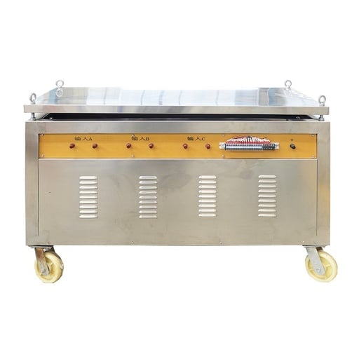
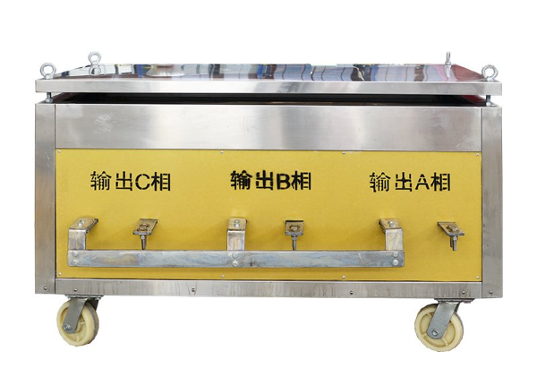
For three-phase switchgear enclosures, busbar trunking systems, and multi-pole circuit breakers, our systems incorporate three independently motorized single-phase induction voltage regulators that are linked to a centralized PLC controller. Independent phase regulation is necessary because spatial conductor geometry and asymmetric magnetic coupling between phases results in unequal loop impedances. The automated closed-loop feedback dynamically trims primary voltage on each phase separately, maintaining balanced continuous current within ±0.5% across phase A, phase B, and phase C simultaneously throughout 24-hour test runs without manual operator rebalancing.

The Thermocouple outputs only produce tens of microvolts per degree Celsius of temperature difference, making them susceptible to temperature difference noise and electromagnetic interference from heavy alternating current (AC) magnetic fields. In contrast, 4-wire Pt100 RTDs operate with constant current excitation to compensate for lead wire resistance variations. Together with shielded twisted-pair cabling and differential galvanic isolation, our instrumentation achieves stable channel accuracy of ±0.5°C in measurement when exposed to strong AC magnetic fields.

Each system is equipped with factory issued Routine Test Certificates, traceable Calibrations for current transformers and temperature loggers, electrical schematics, PLC ladder logic, and a complete Operation manual.

Hardware-based multi-layer safety interlocking with zero-start protection (preventing voltage energization unless regulator is at zero position) and overcurrent fast-trip relays (trips within 20 milliseconds) are included in our design. So is emergency shutdown due to specimen overtemperature, cooling fan airflow interlocks, and emergency stop circuits. The system logs an event if any of the monitored points goes above the programmed emergency limits, and safe-trips the main primary power in the process.

When you purchase equipment, you can request on-site commissioning service, and we will send commissioning engineers to your facility around the world. Our engineers will supervise equipment positioning, link high current busbar connections, commission utility power supplies, calibrate thermal channels, and give hands-on training to your test operators using your production switchgear specimens in full accordance with IEC 62271-1 standards. On-site engineering service fees are determined by the number of engineers and duration of service required.